For this clock project, I’m using a Raspberry Pi Pico, but the code should be easily ported to any other microcontroller, as the functionality of the clock itself is basic. The Raspberry Pi Pico has a built-in RTC so results easier to implement the clock. Other Microcontrollers with Wifi Capabilities could also obtain the clock data from a web service instead of an intrnal RTC making the board capabilities more atractive as weather or many other kind of IOT notificaions.
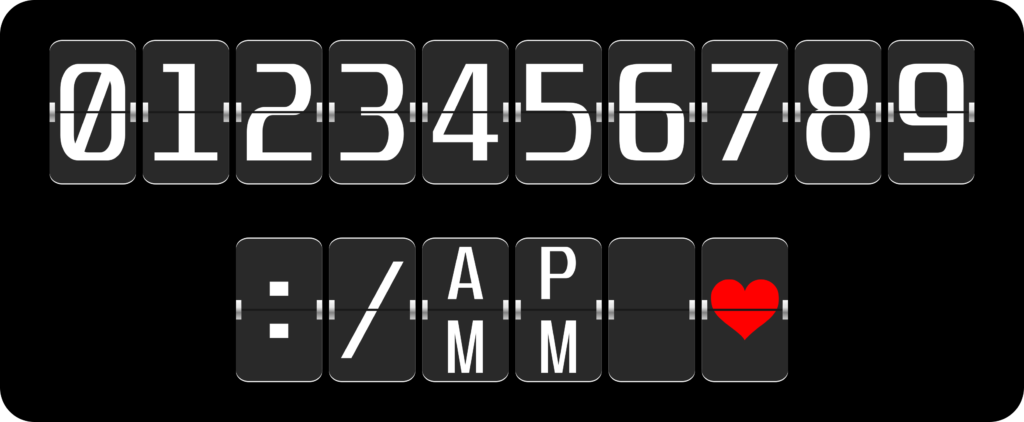
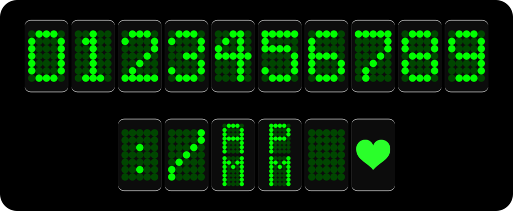
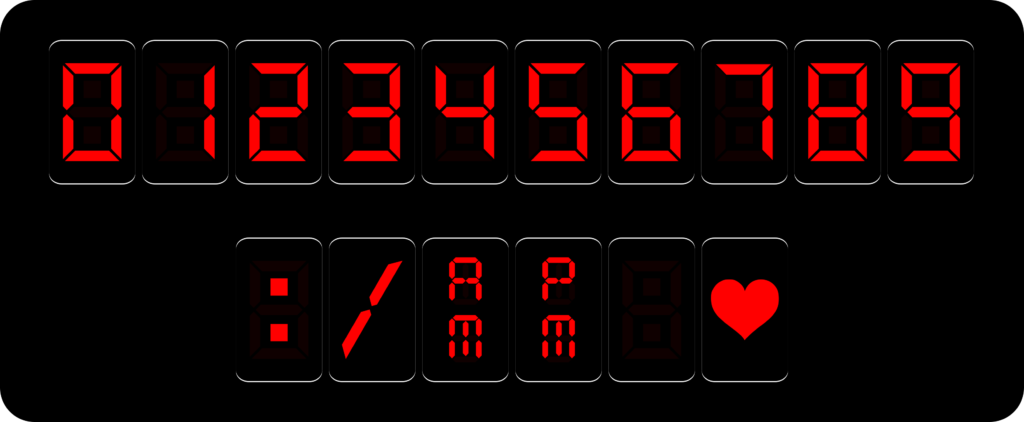
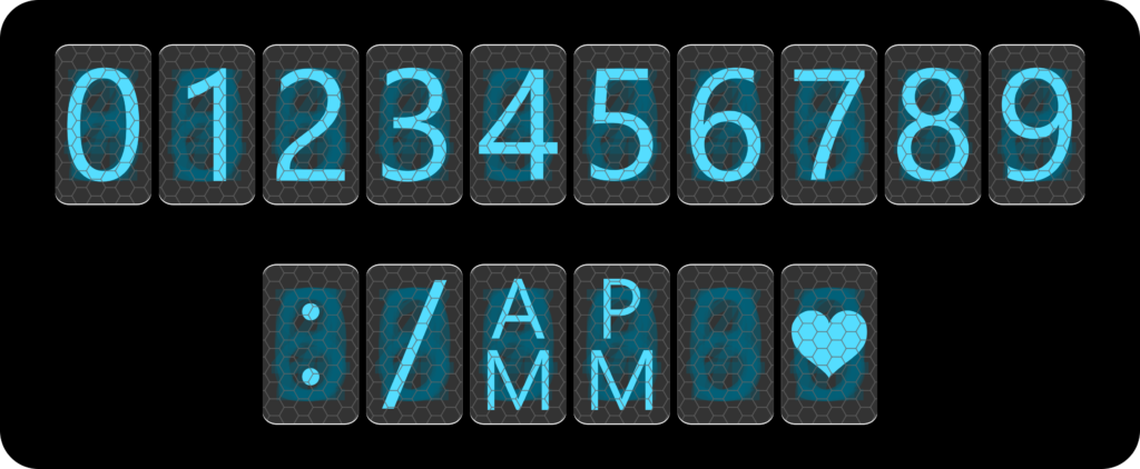
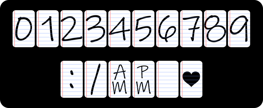
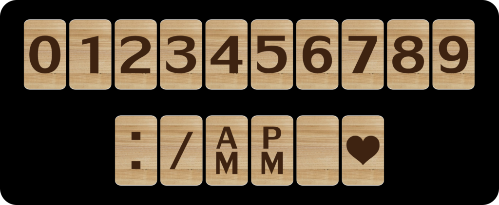
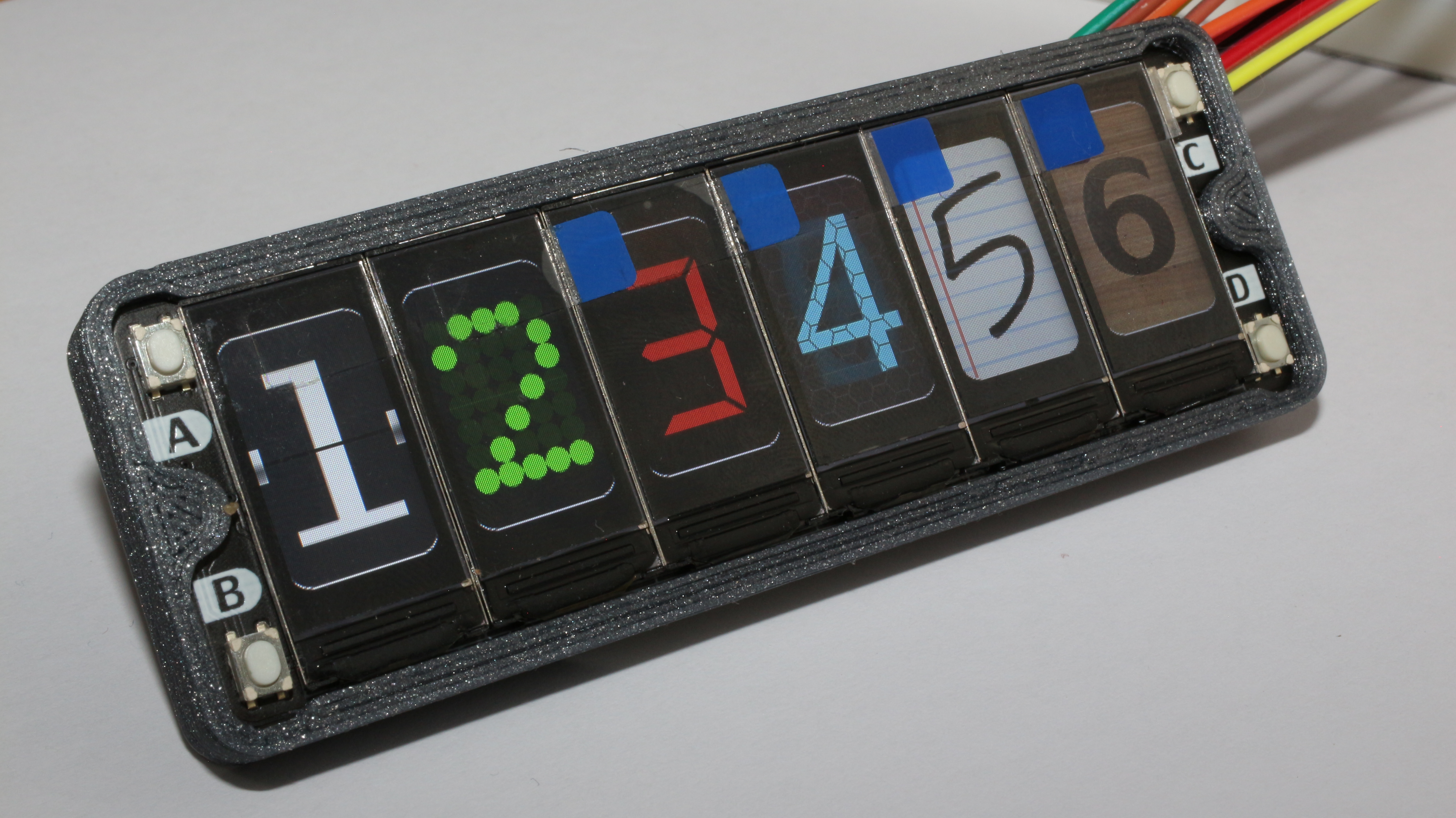
The firmware uses already converted images to have the nicest look, this could also be done with a Numerical Font and interchangeable backgrounds but I think it would not look this great.
For the image conversion, I use the software LCD Image Converter which is a very useful piece of software, fo the displays in the Display Array Board I use RGB565 and copy the data to *.h file in my project.
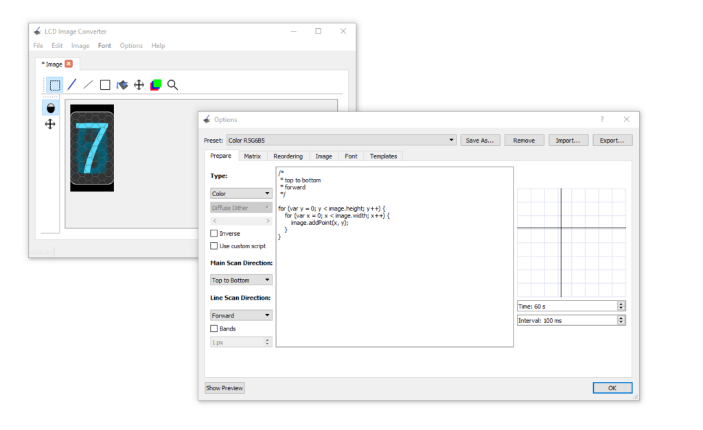
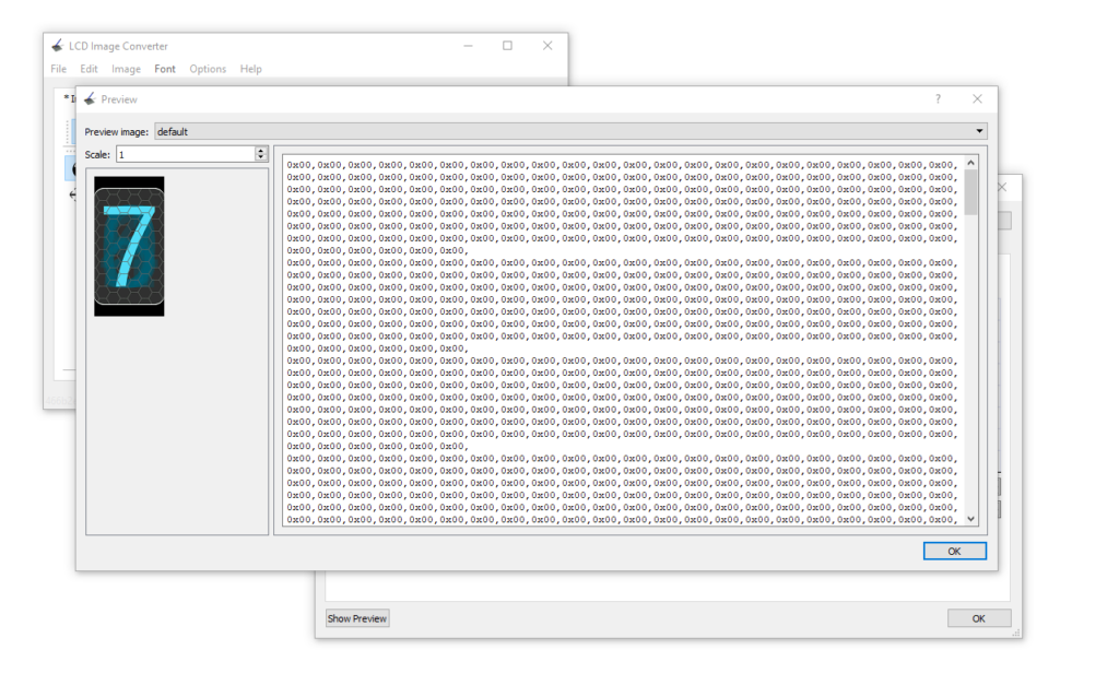
By clicking the button Show Preview we have access to the data Image to add to our project and send it to the display.
After converting all the images for the clock we just need to call the corresponding image and send it to the corresponding display, for this, I have just used some simple if statements.
if(t.hour >= 1 & t.hour <= 9){
lcdDrawNumber(pio,sm,display1,0);
lcdDrawNumber(pio,sm,display2,t.hour);
}else if(t.hour >= 10 & t.hour <= 12){
lcdDrawNumber(pio,sm,display1,1);
lcdDrawNumber(pio,sm,display2,t.hour-10);
}else if(t.hour >= 13 & t.hour <= 21){
lcdDrawNumber(pio,sm,display1,0);
lcdDrawNumber(pio,sm,display2,t.hour-12);
}else if(t.hour >= 22 ){
lcdDrawNumber(pio,sm,display1,1);
lcdDrawNumber(pio,sm,display2,t.hour-22);
}else if (t.hour == 0){
lcdDrawNumber(pio,sm,display1,1);
lcdDrawNumber(pio,sm,display2,2);
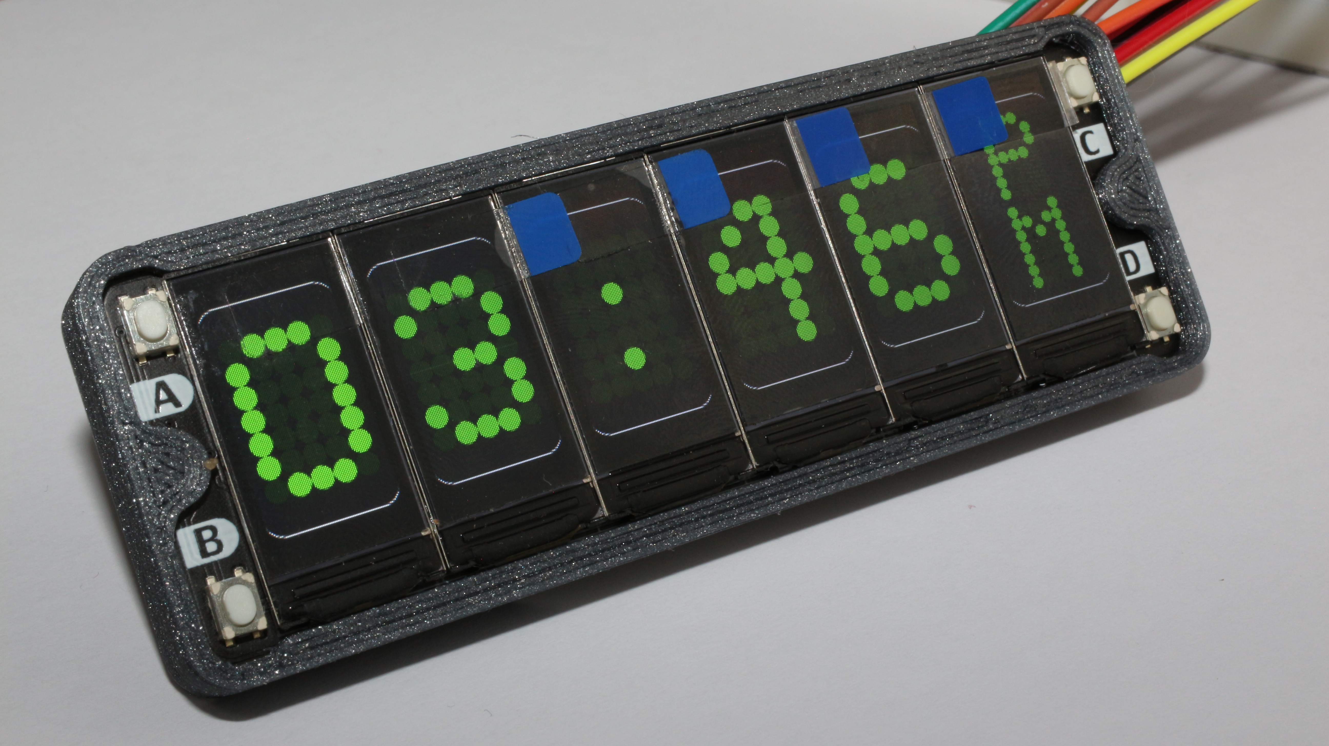
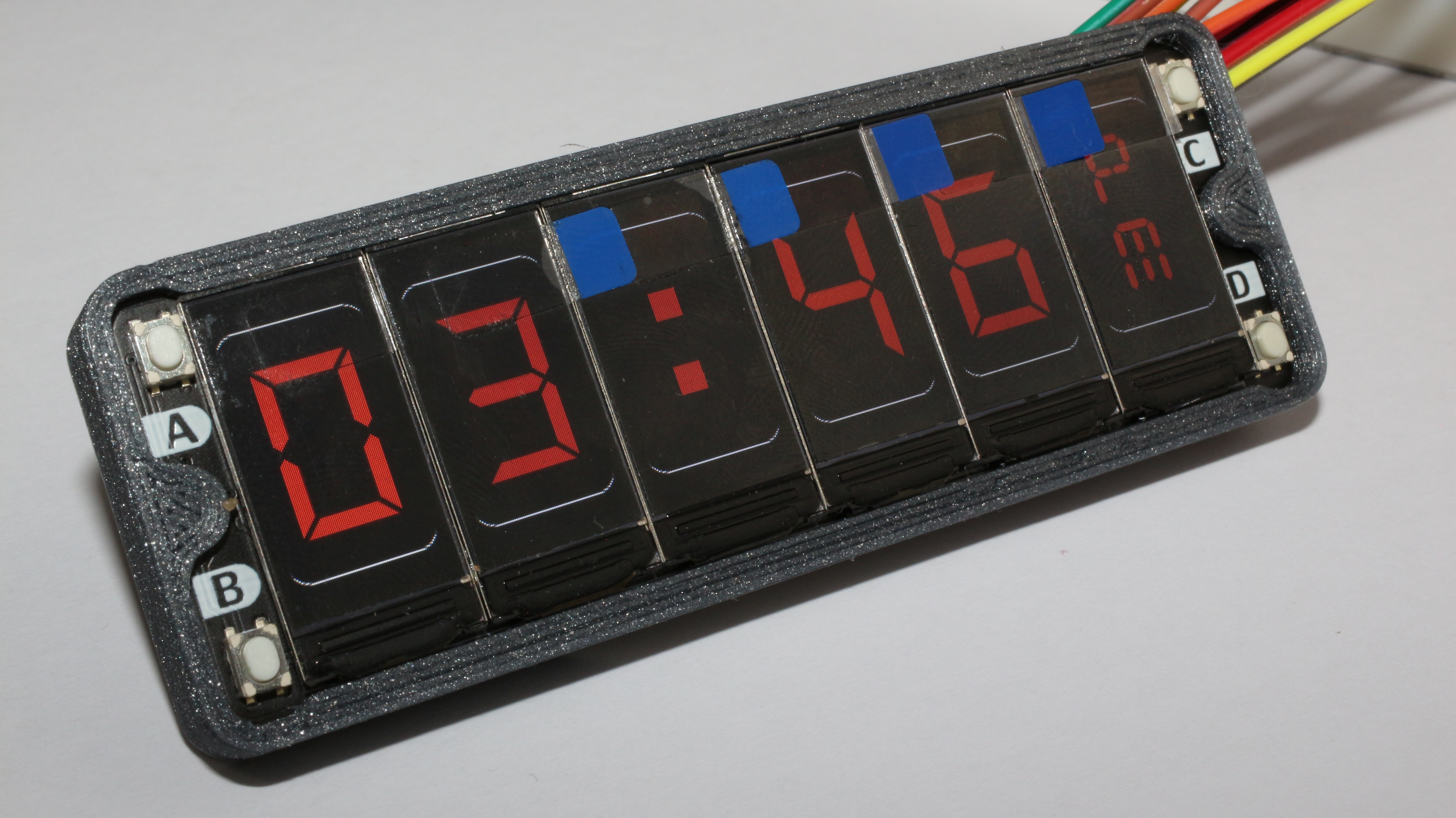
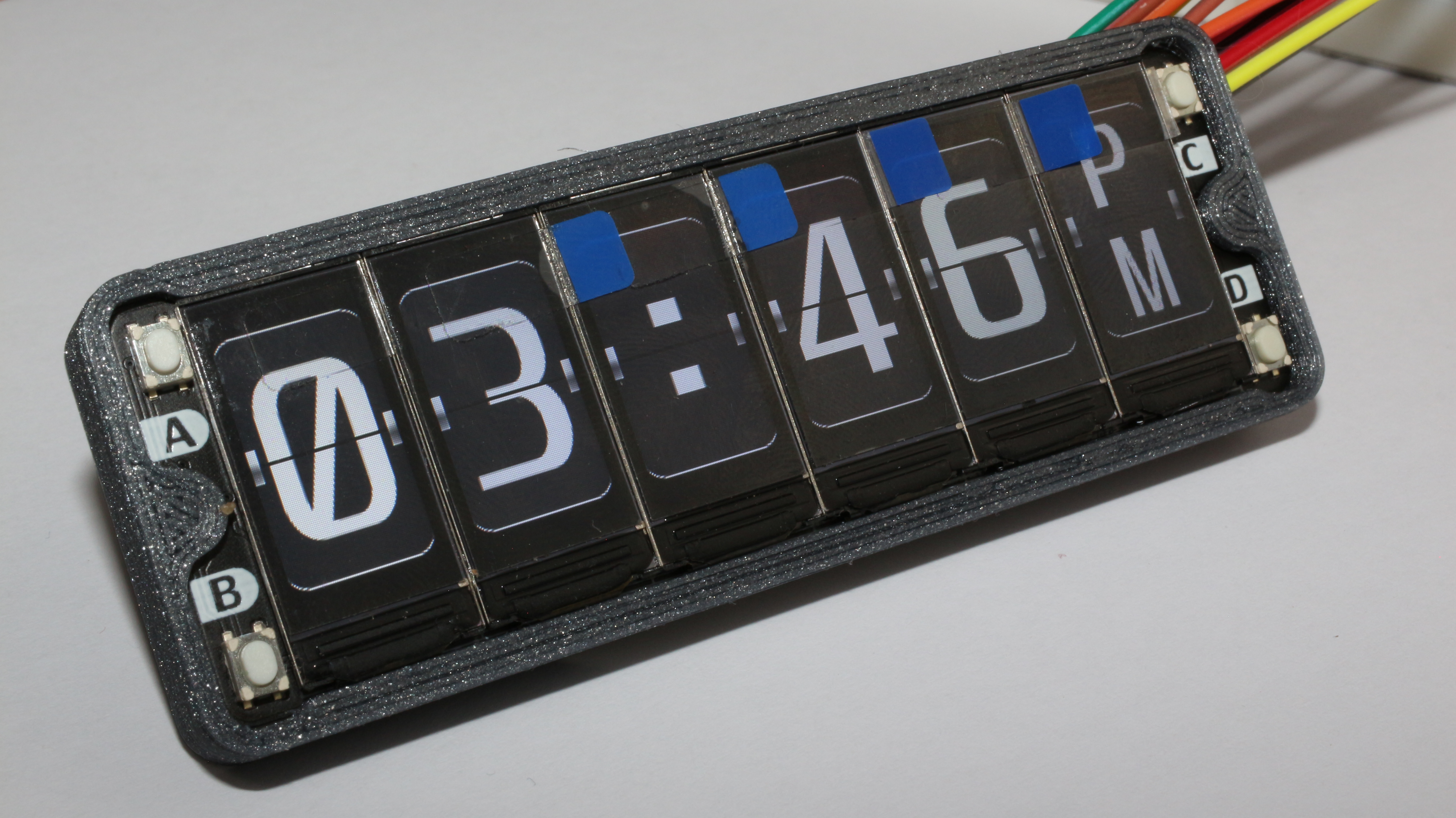
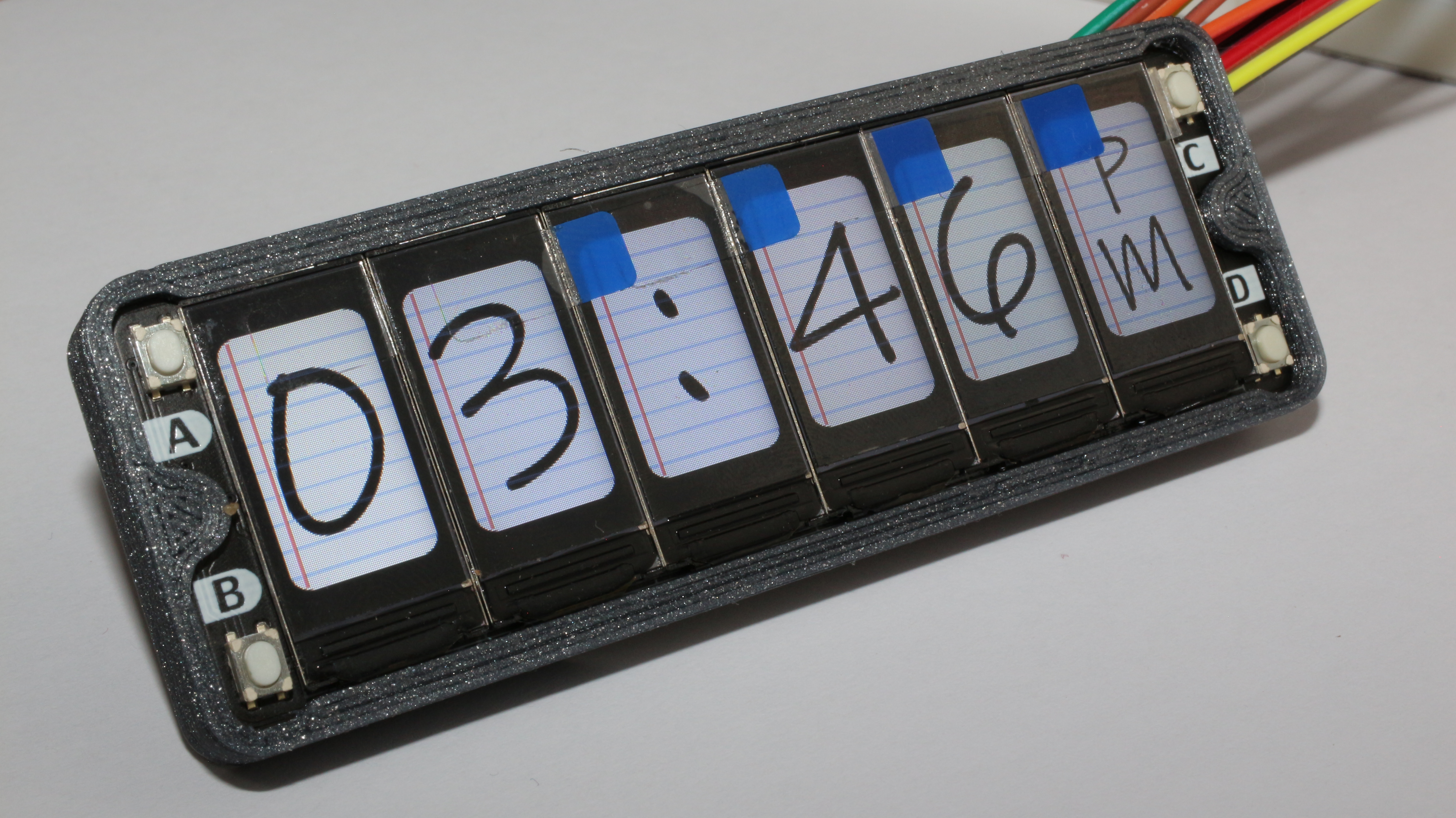
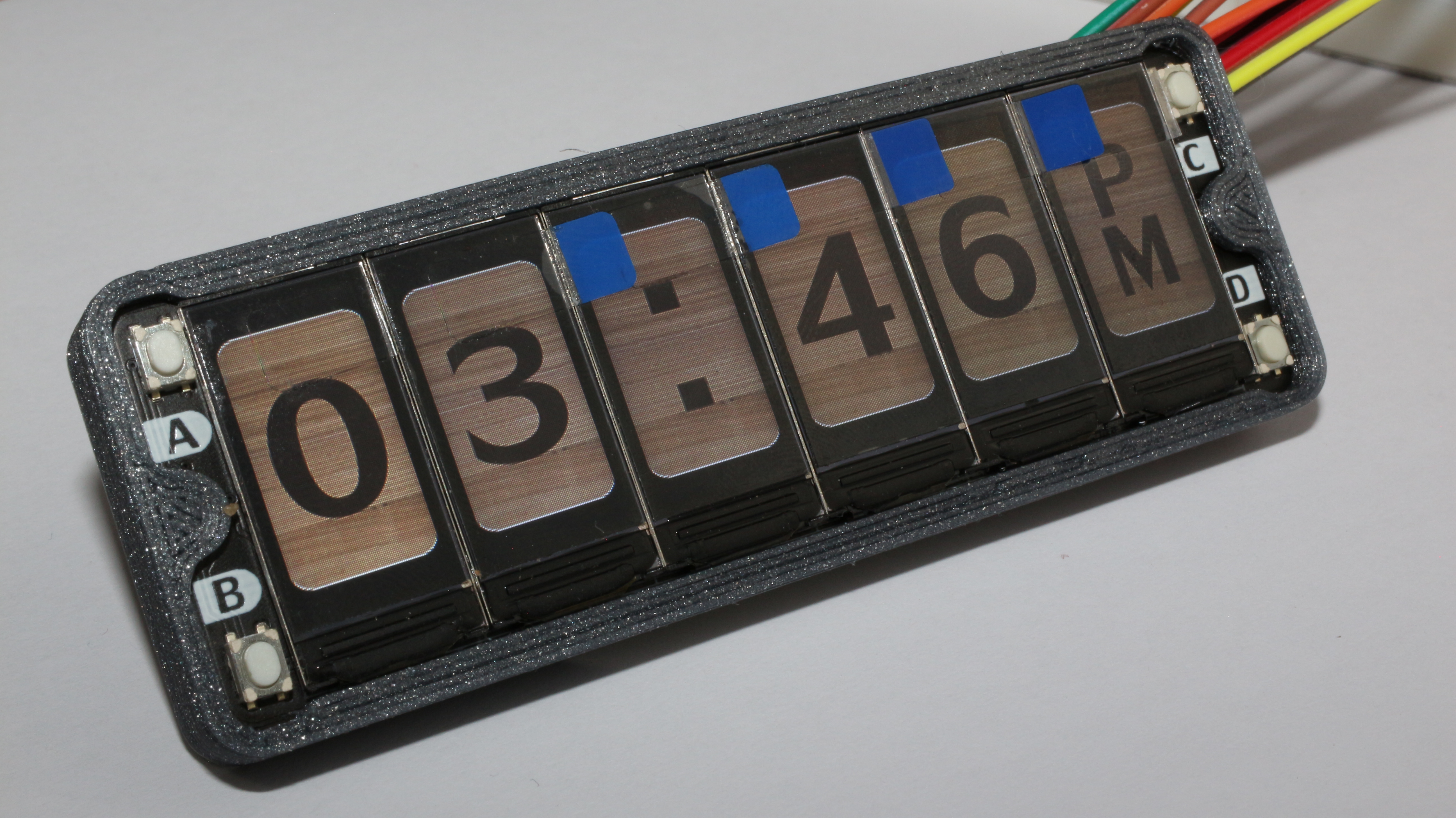
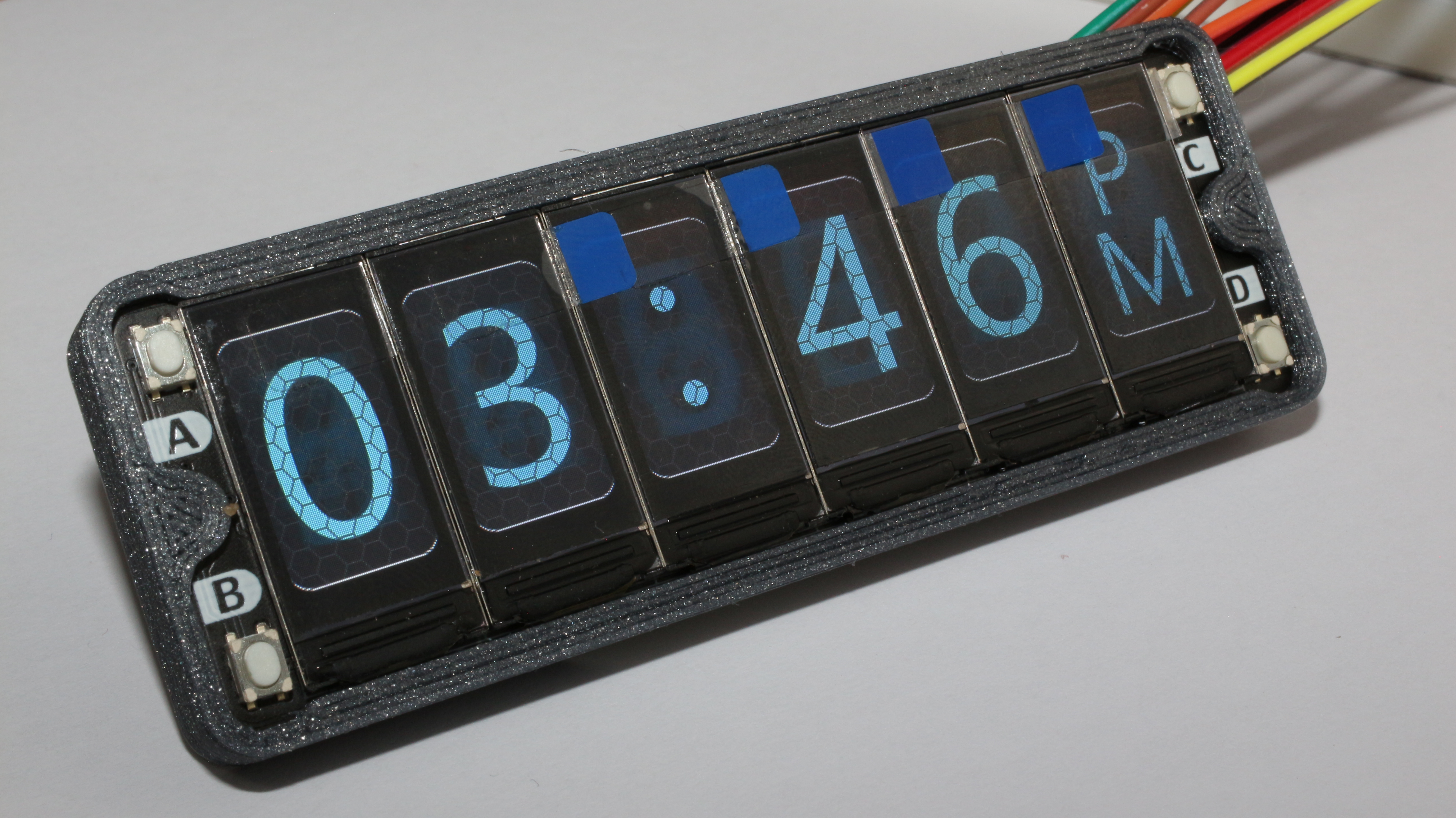
}After doing this for minutes, AM, and PM screens we can add some animations by sending the Space image and the colon symbol image at different rates, and also this can be applied to the configuration state of the clock.
if(ConfigureTime_MODE == OFF){
lcdDrawNumber(pio,sm,display3,COLON);
sleep_ms(500);
lcdDrawNumber(pio,sm,display3,SPACE);
sleep_ms(500);
}else{
if(Selection == HRS){
sleep_ms(200);
lcdDrawNumber(pio,sm,display1,SPACE);
lcdDrawNumber(pio,sm,display2,SPACE);
lcdDrawNumber(pio,sm,display3,COLON);
sleep_ms(200);
}else if(Selection == MINS){
sleep_ms(200);
lcdDrawNumber(pio,sm,display3,COLON);
lcdDrawNumber(pio,sm,display4,SPACE);
lcdDrawNumber(pio,sm,display5,SPACE);
sleep_ms(200);
}
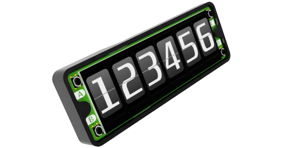
}Resulting in an animation like the following:
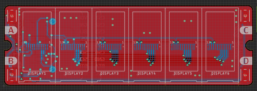
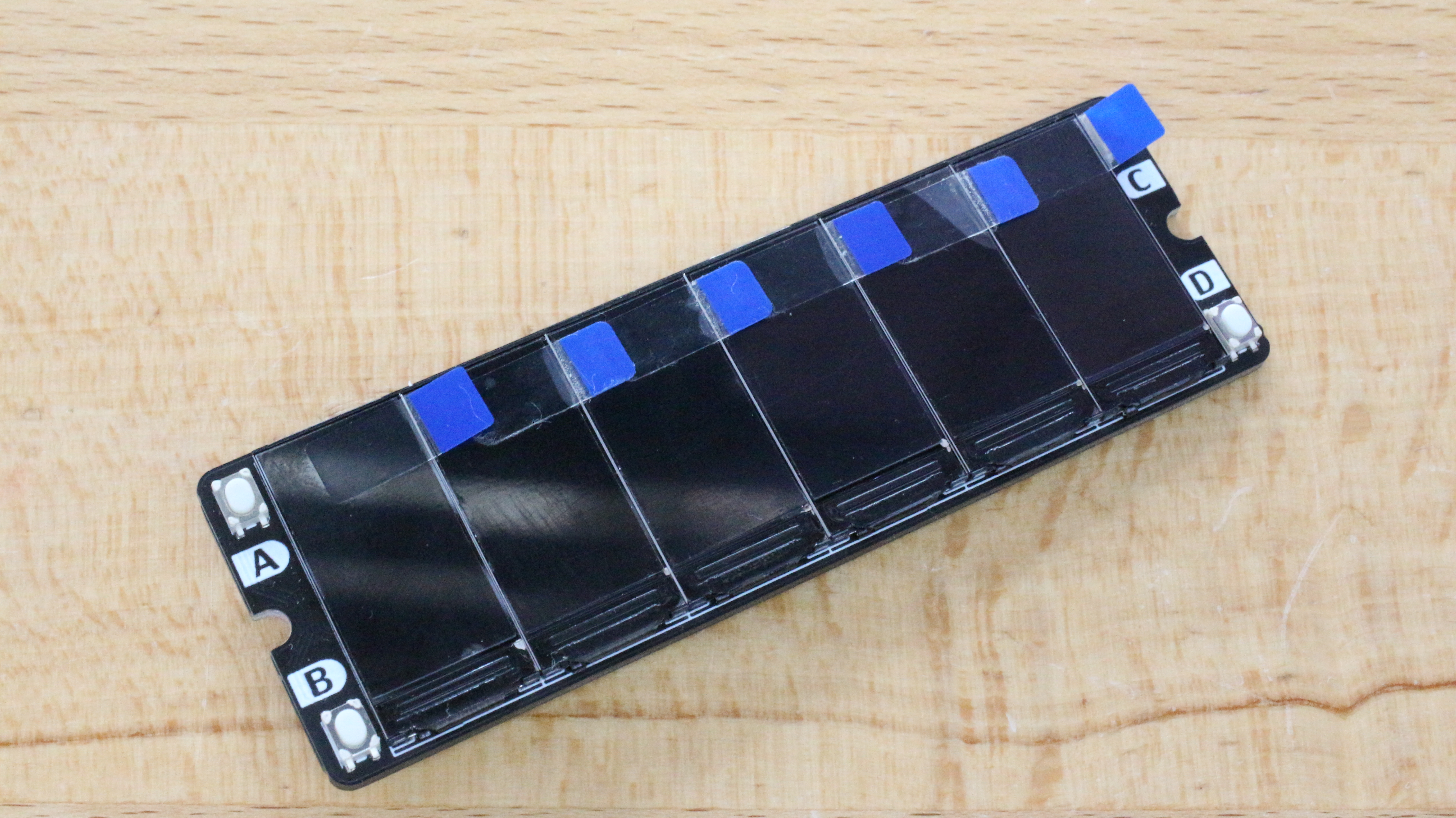
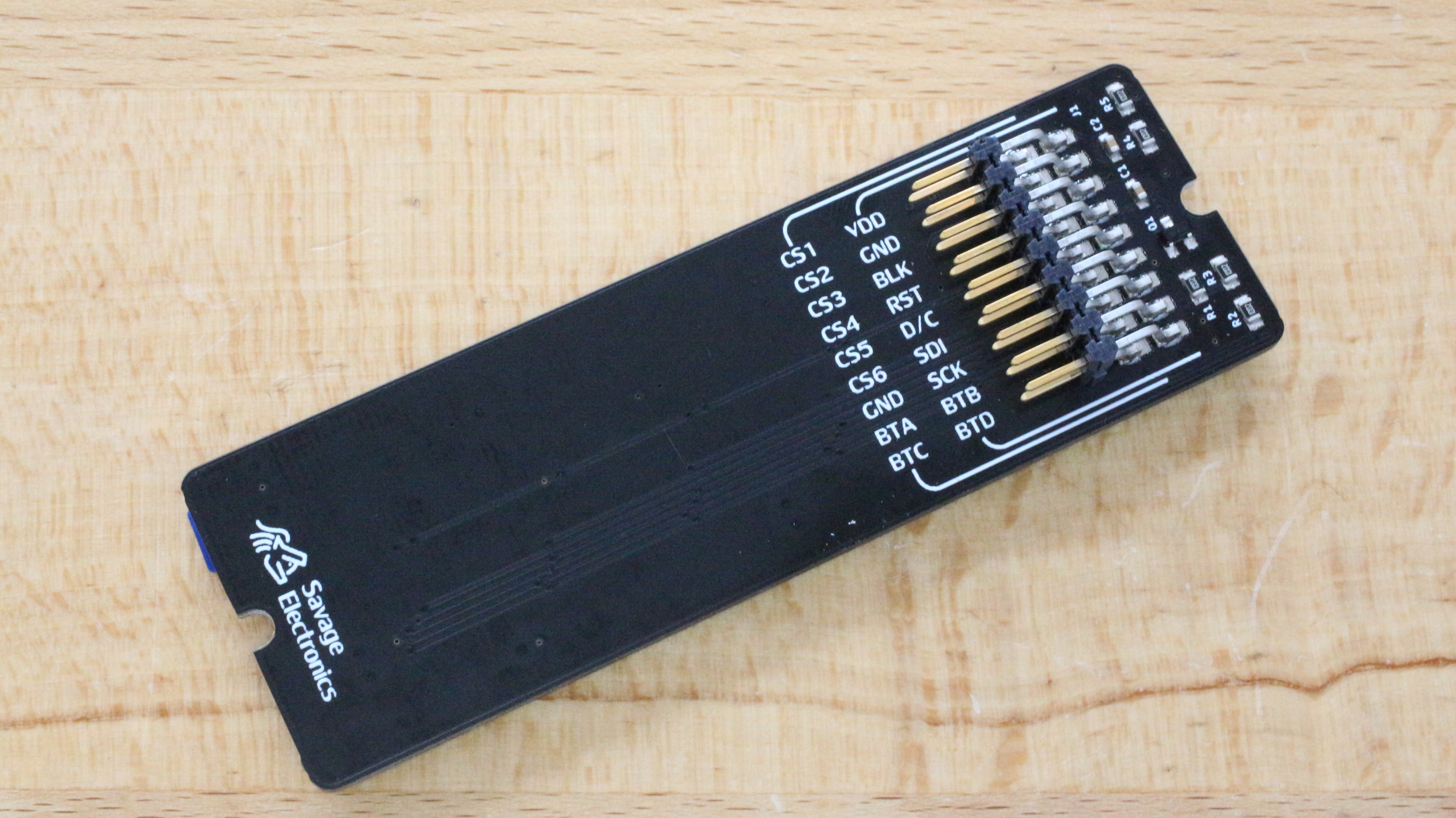
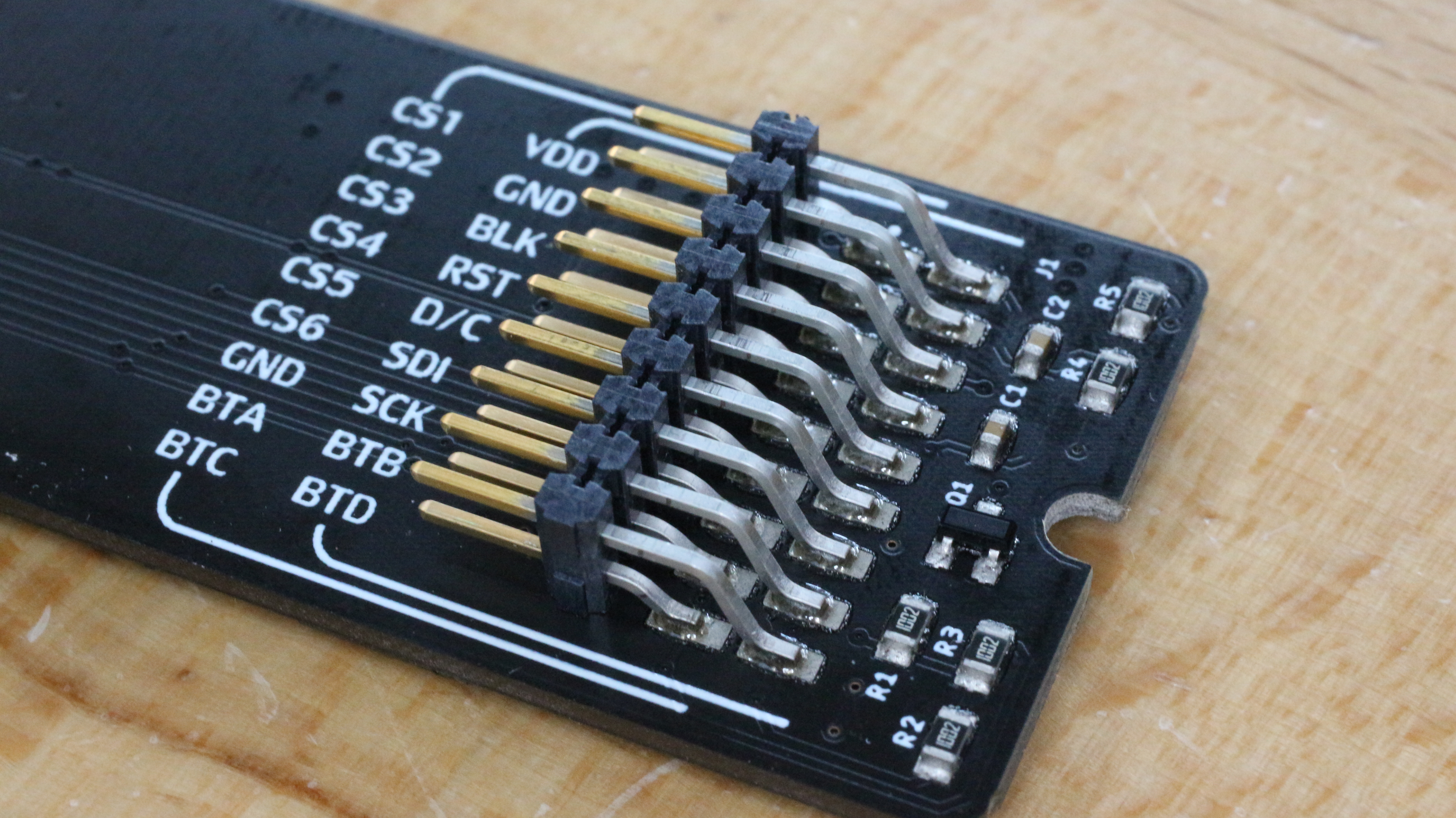
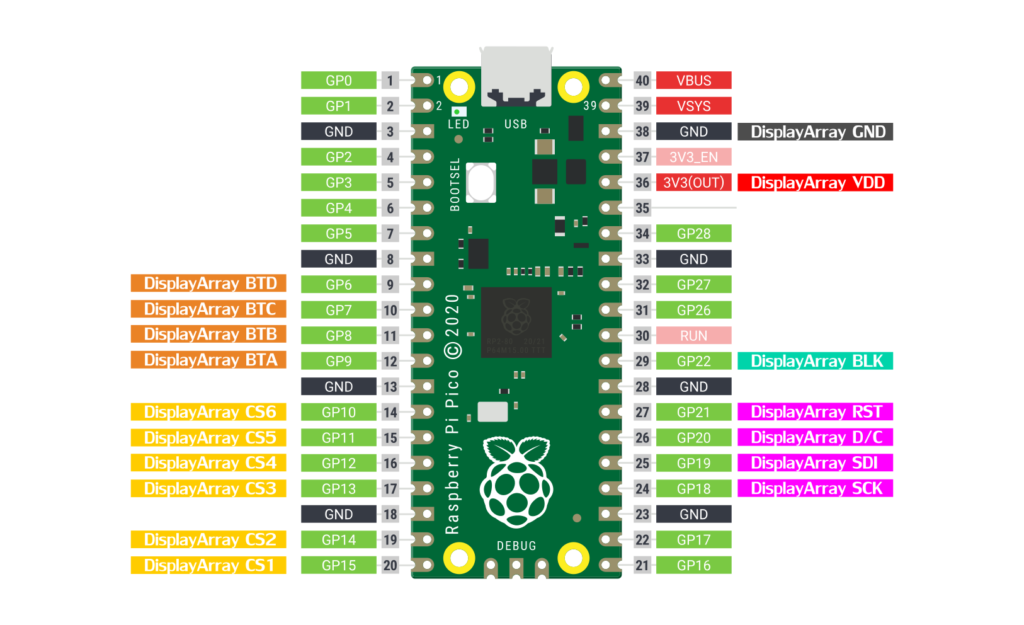
Raspberry Pi Pico connection with Display Array Board
Posible error in the Pico SDK
There is a chance that your pico-SDK has an error and the program would not start. In your SDK directory: pico-sdk/src/common/pico_time/time.c file comment line 17, //CU_SELECT_DEBUG_PINS(core) and now the program should run with any problem.
#include <limits.h>
#include <stdio.h>
#include <stdlib.h>
#include "pico.h"
#include "pico/time.h"
#include "pico/util/pheap.h"
#include "hardware/sync.h"
#include "hardware/gpio.h"

CU_REGISTER_DEBUG_PINS(core)
//CU_SELECT_DEBUG_PINS(core) //Comment this line for RTC troubles

const absolute_time_t ABSOLUTE_TIME_INITIALIZED_VAR(nil_time, 0);
// use LONG_MAX not ULONG_MAX so we don't have sign overflow in time diffs
const absolute_time_t ABSOLUTE_TIME_INITIALIZED_VAR(at_the_end_of_time, ULONG_MAX);

typedef struct alarm_pool_entry {
    absolute_time_t target;
    alarm_callback_t callback;
    void *user_data;
} alarm_pool_entry_t;
Below you can download the source code of this clock and also the Precompiled UF2 File. The media files can be downloaded on the previous post.