I decided to update some of the clock faces to make them simpler and easier to read. There also some faces that were asked in the maker community. The previous designs will be still available to download at any time in the SPI Display Array main post.
For this clock project, I’m using a Raspberry Pi Pico, but the code should be easily ported to any other microcontroller, as the functionality of the clock itself is basic. The Raspberry Pi Pico has a built-in RTC so results easier to implement the clock. Other Microcontrollers with Wifi Capabilities could also obtain the clock data from a web service instead of an intrnal RTC making the board capabilities more atractive as weather or many other kind of IOT notificaions.
The firmware uses already converted images to have the nicest look, this could also be done with a Numerical Font and interchangeable backgrounds but I think it would not look this great.
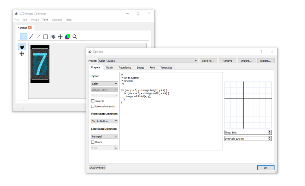
For the image conversion, I use the software LCD Image Converter which is a very useful piece of software, fo the displays in the Display Array Board I use RGB565 and copy the data to *.h file in my project.
Image conversion
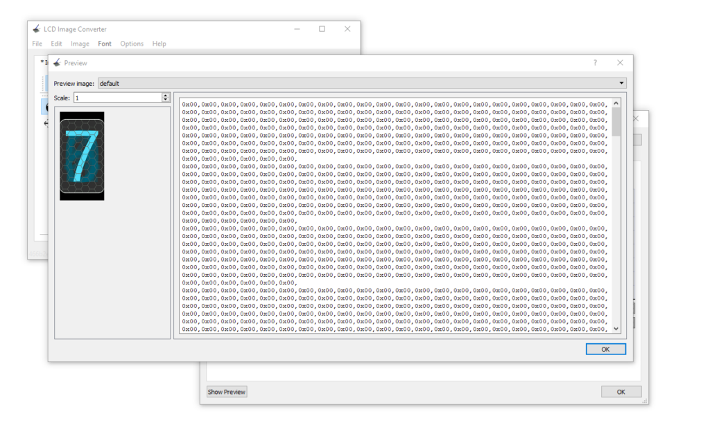
By clicking the button Show Preview we have access to the data Image to add to our project and send it to the display.
Image Data
After converting all the images for the clock we just need to call the corresponding image and send it to the corresponding display, for this, I have just used some simple if statements.
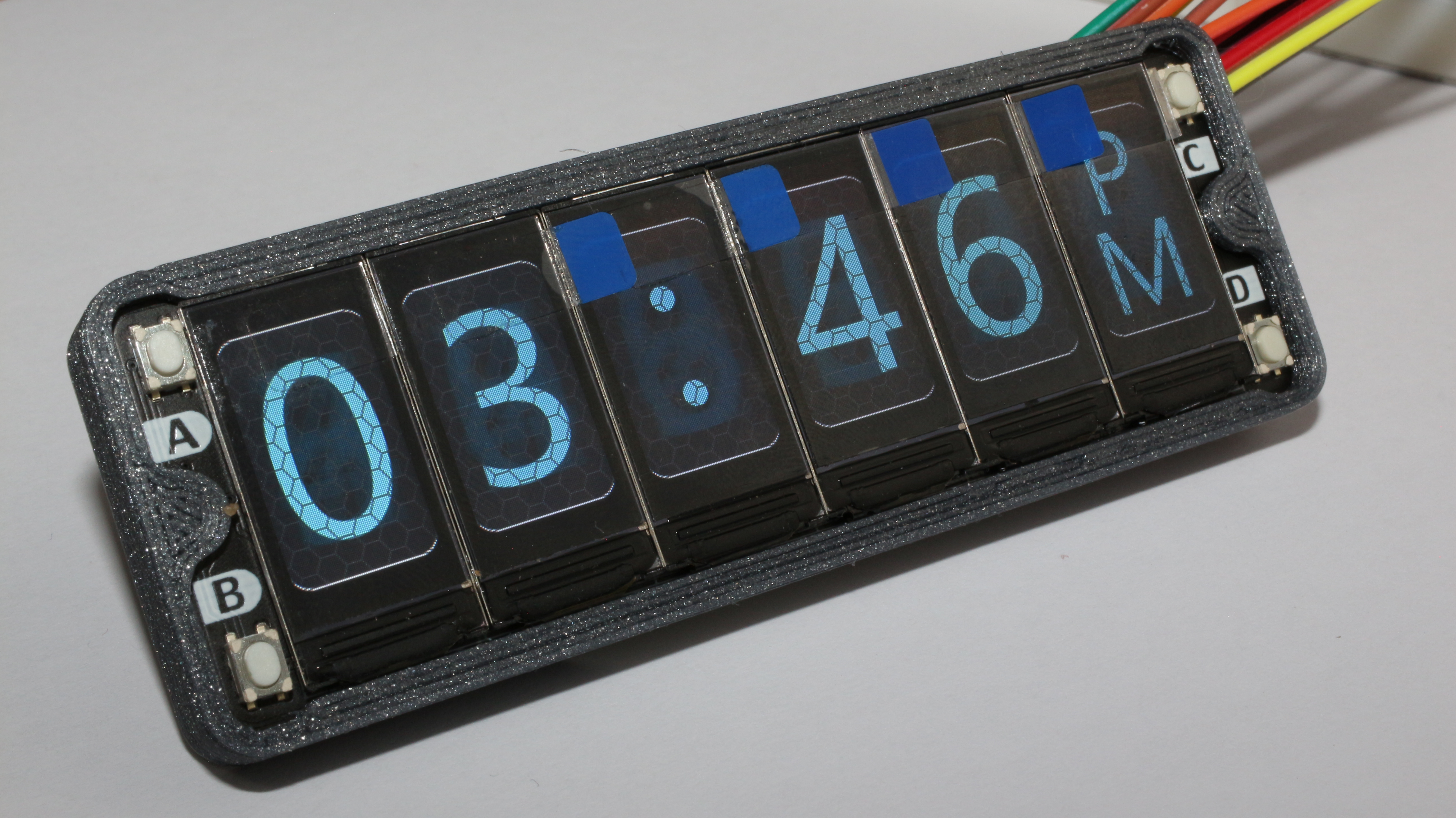
After doing this for minutes, AM, and PM screens we can add some animations by sending the Space image and the colon symbol image at different rates, and also this can be applied to the configuration state of the clock.
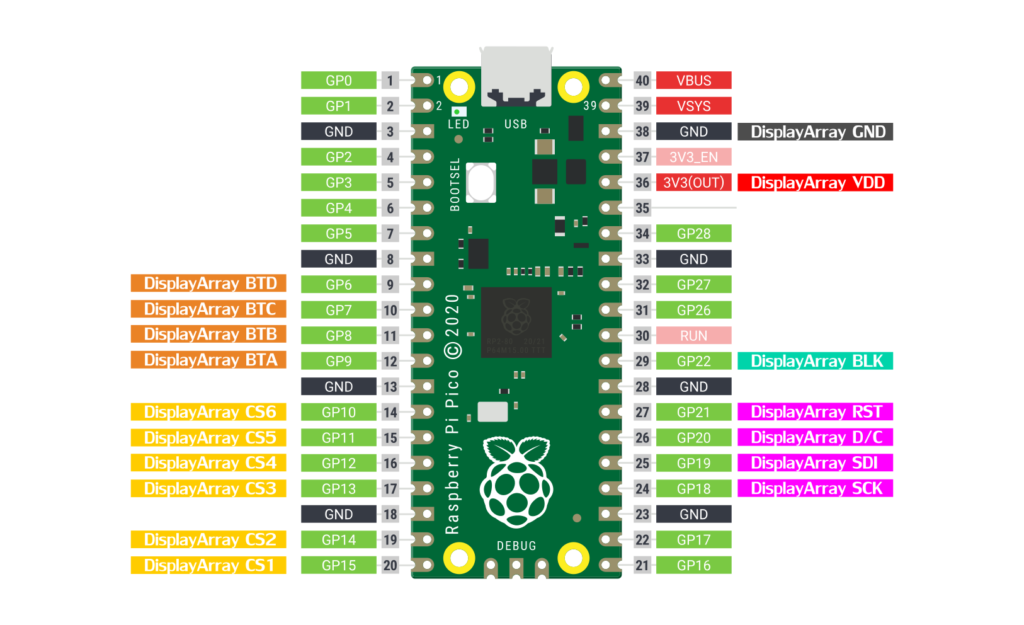
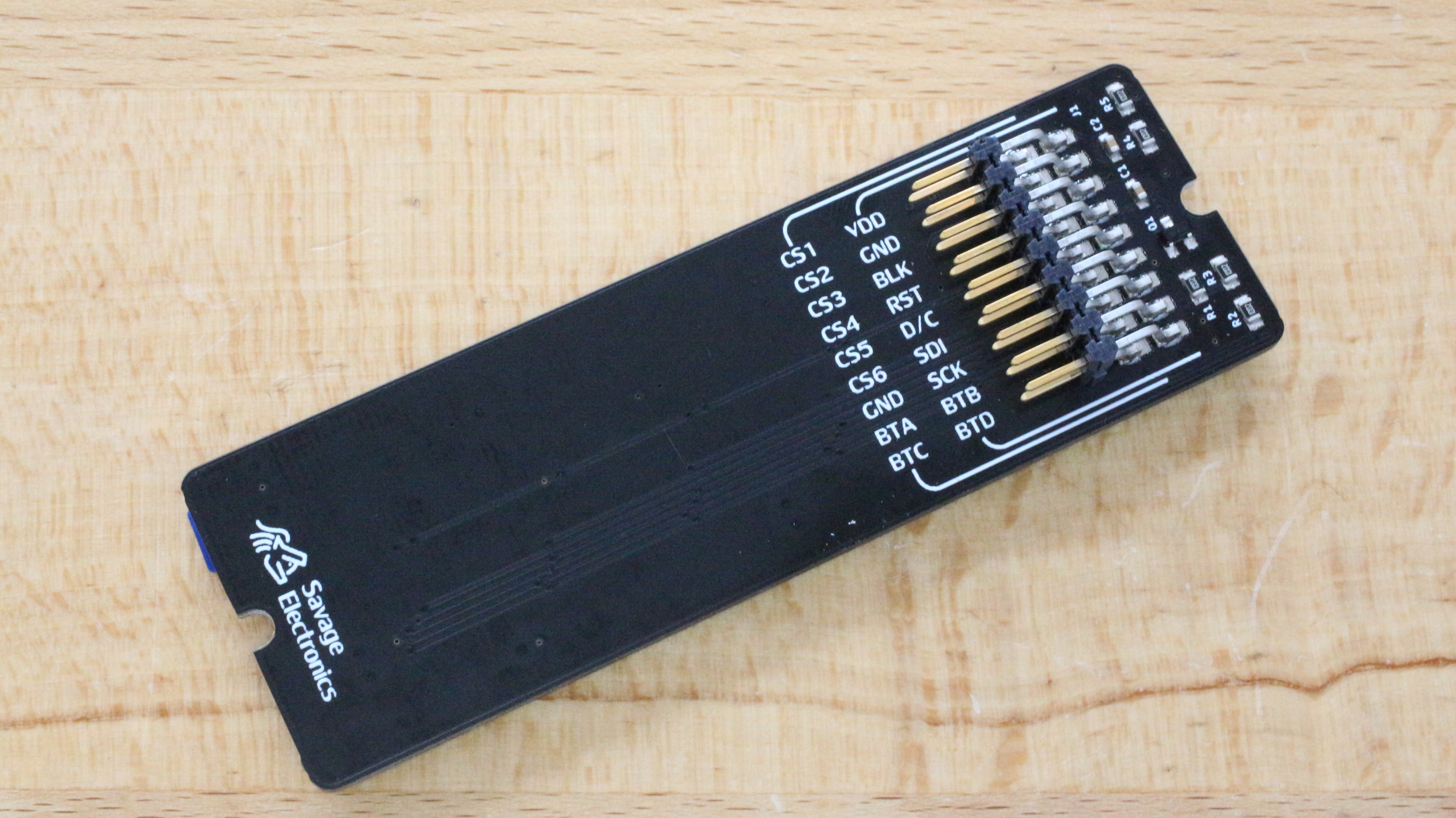
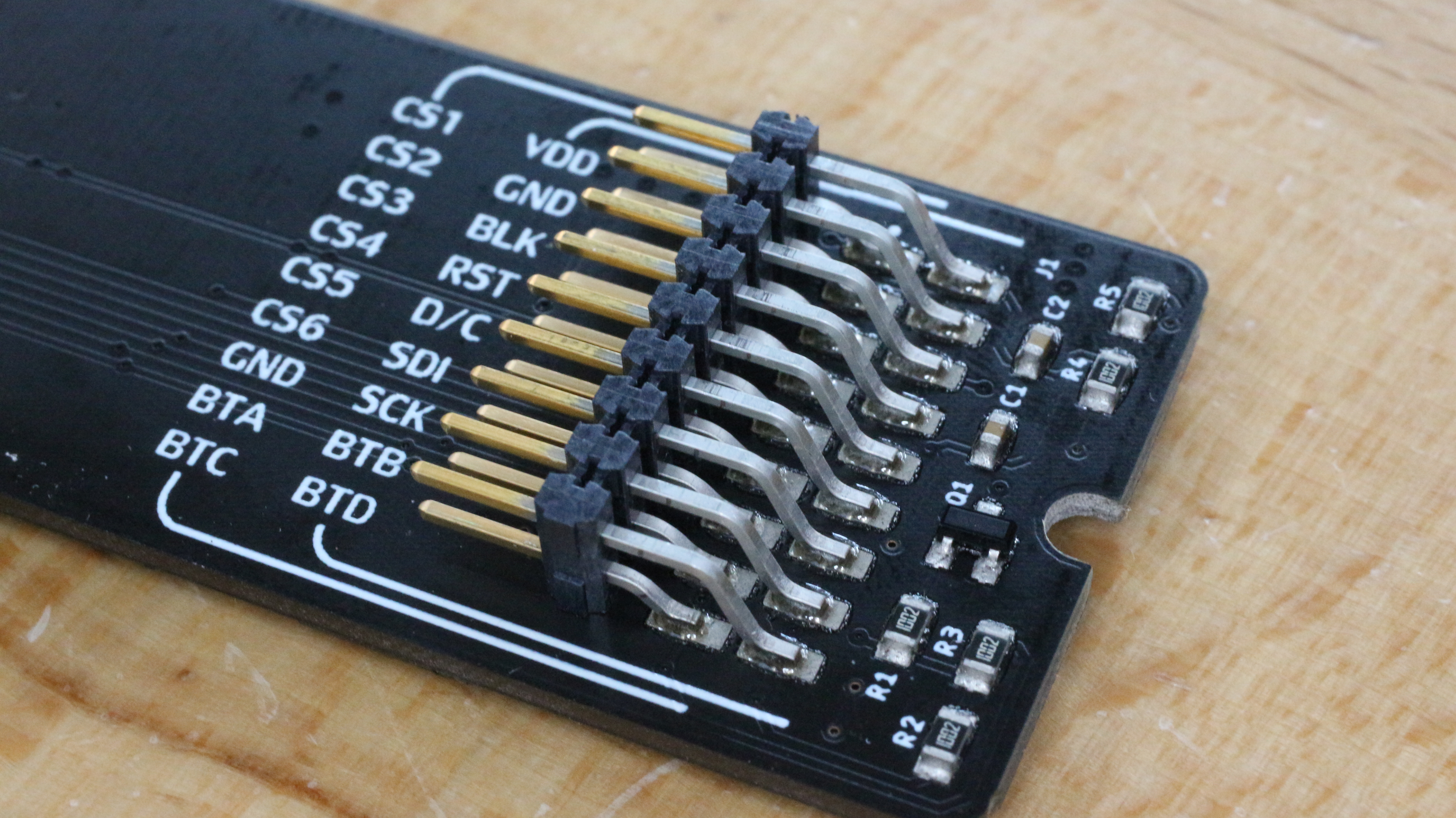
Raspberry Pi Pico connection with Display Array Board
Raspberry Pi Pico and Display Array Board
Posible error in the Pico SDK
There is a chance that your pico-SDK has an error and the program would not start. In your SDK directory: pico-sdk/src/common/pico_time/time.c file comment line 17, //CU_SELECT_DEBUG_PINS(core) and now the program should run with any problem.
#include <limits.h>
#include <stdio.h>
#include <stdlib.h>
#include "pico.h"
#include "pico/time.h"
#include "pico/util/pheap.h"
#include "hardware/sync.h"
#include "hardware/gpio.h"

CU_REGISTER_DEBUG_PINS(core)
//CU_SELECT_DEBUG_PINS(core) //Comment this line for RTC troubles

const absolute_time_t ABSOLUTE_TIME_INITIALIZED_VAR(nil_time, 0);
// use LONG_MAX not ULONG_MAX so we don't have sign overflow in time diffs
const absolute_time_t ABSOLUTE_TIME_INITIALIZED_VAR(at_the_end_of_time, ULONG_MAX);

typedef struct alarm_pool_entry {
    absolute_time_t target;
    alarm_callback_t callback;
    void *user_data;
} alarm_pool_entry_t;
Below you can download the source code of this clock and also the Precompiled UF2 File. The media files can be downloaded on the previous post.
The main idea of this project was to make a customizable clock, a clock that would have the option to change its appearance very easily, The first option was to make it with RGB LEDs and change the color at will, maybe to have the ability to change the color according to the time of the day or with the ambient temperature, but what is more customizable than a display by itself, nowadays we can find very nice IPS Displays that are very cheap.
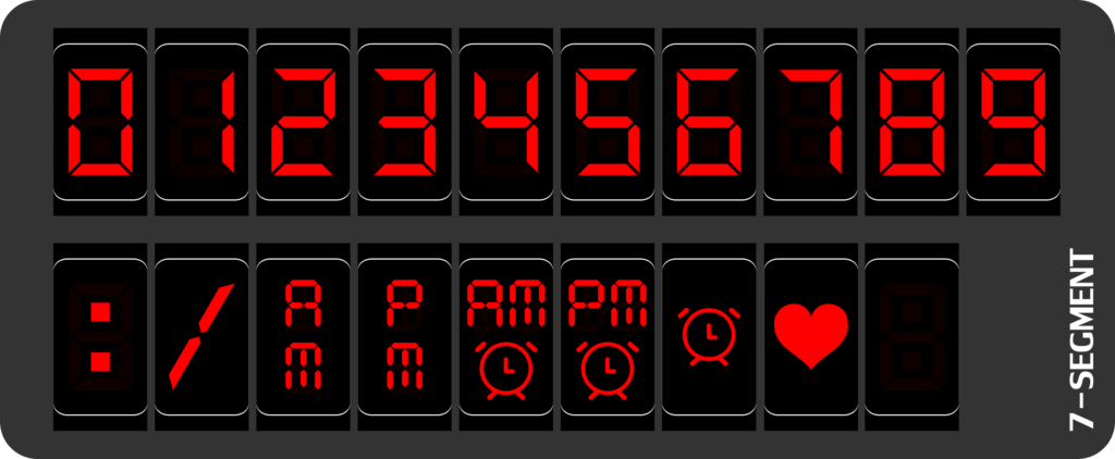
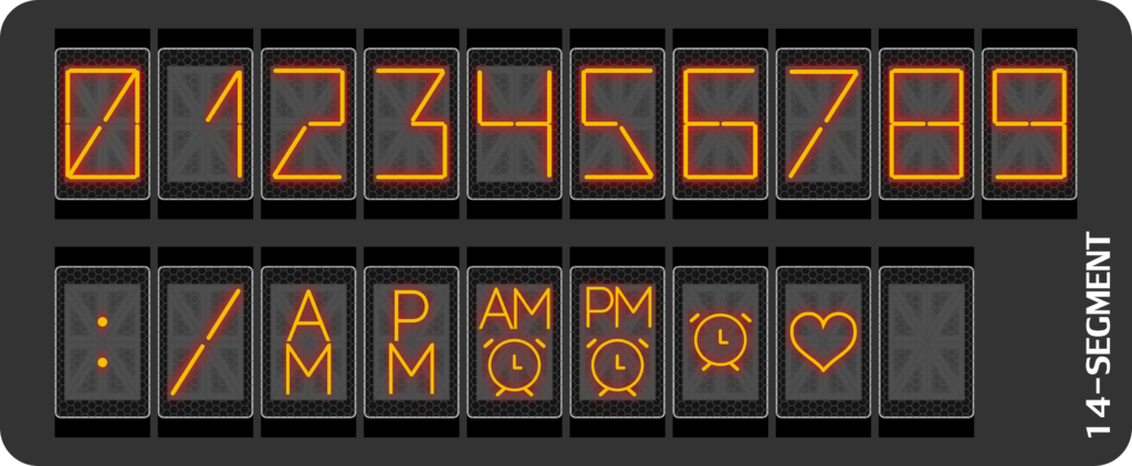
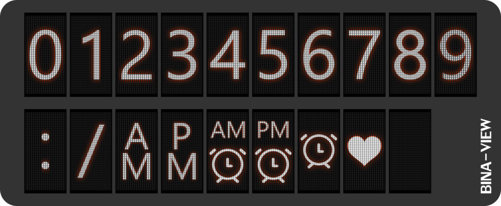
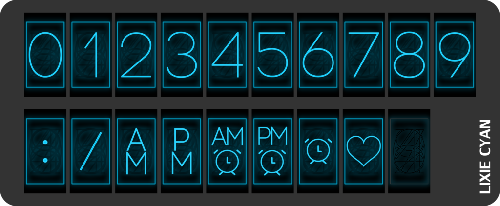
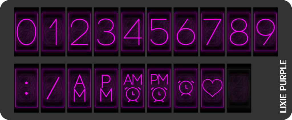
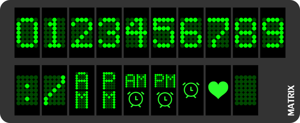
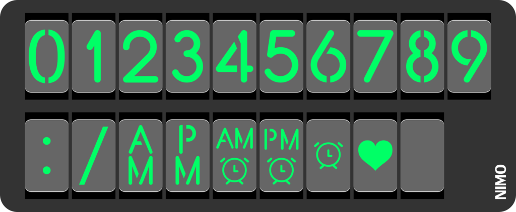
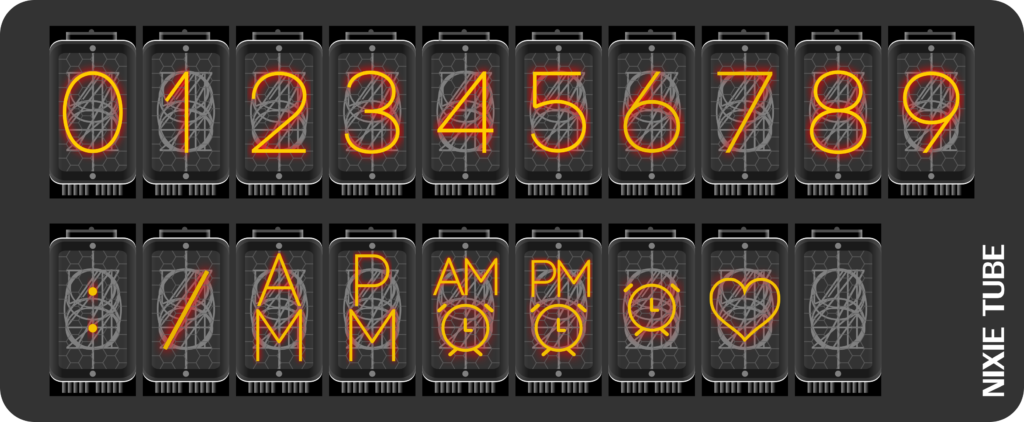
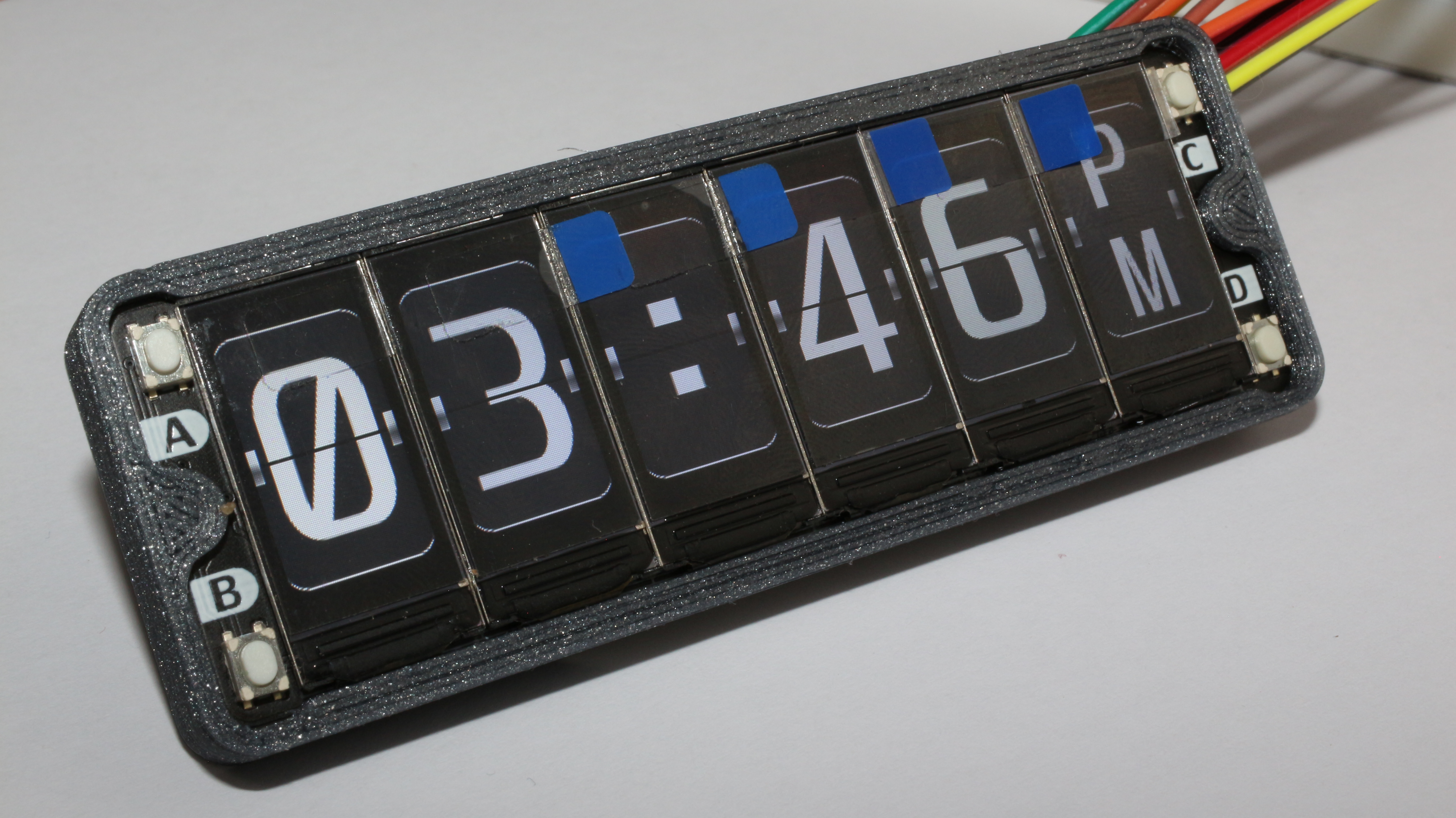
Maybe the hardest step of this project was the clock creation, making the graphics for each clock was really challenging as I wanted to look very similar to the real ones, like the Flip Clock, the seven-segment Display clock, the LED matrix clock.
These are only a few clocks that I have created, but it will be awesome to see other designs and that is why I’m sharing the design files of this project, I think it would be awesome to see how a project can evolve in the maker community.
I have also designed a 3D printed enclosure or in this case a frame. It consists of only 3 parts that glued together to make a single clock piece.
3D Printed clock bracket
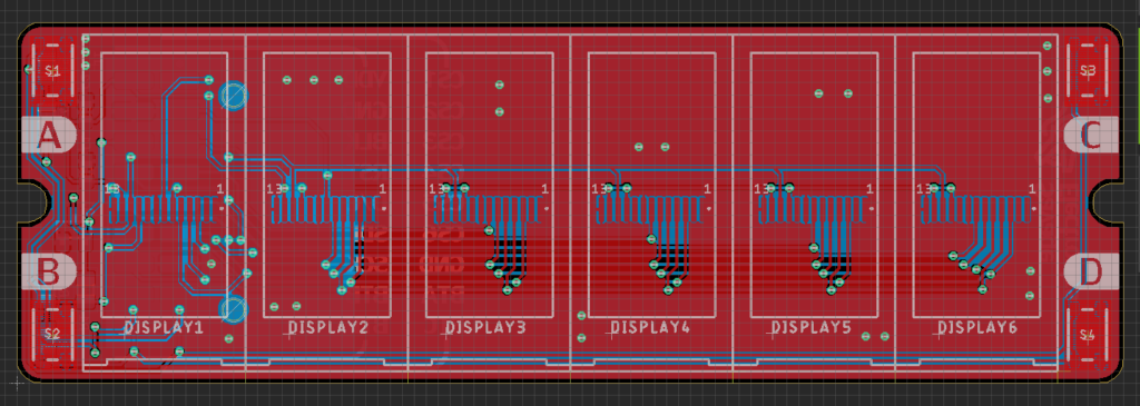
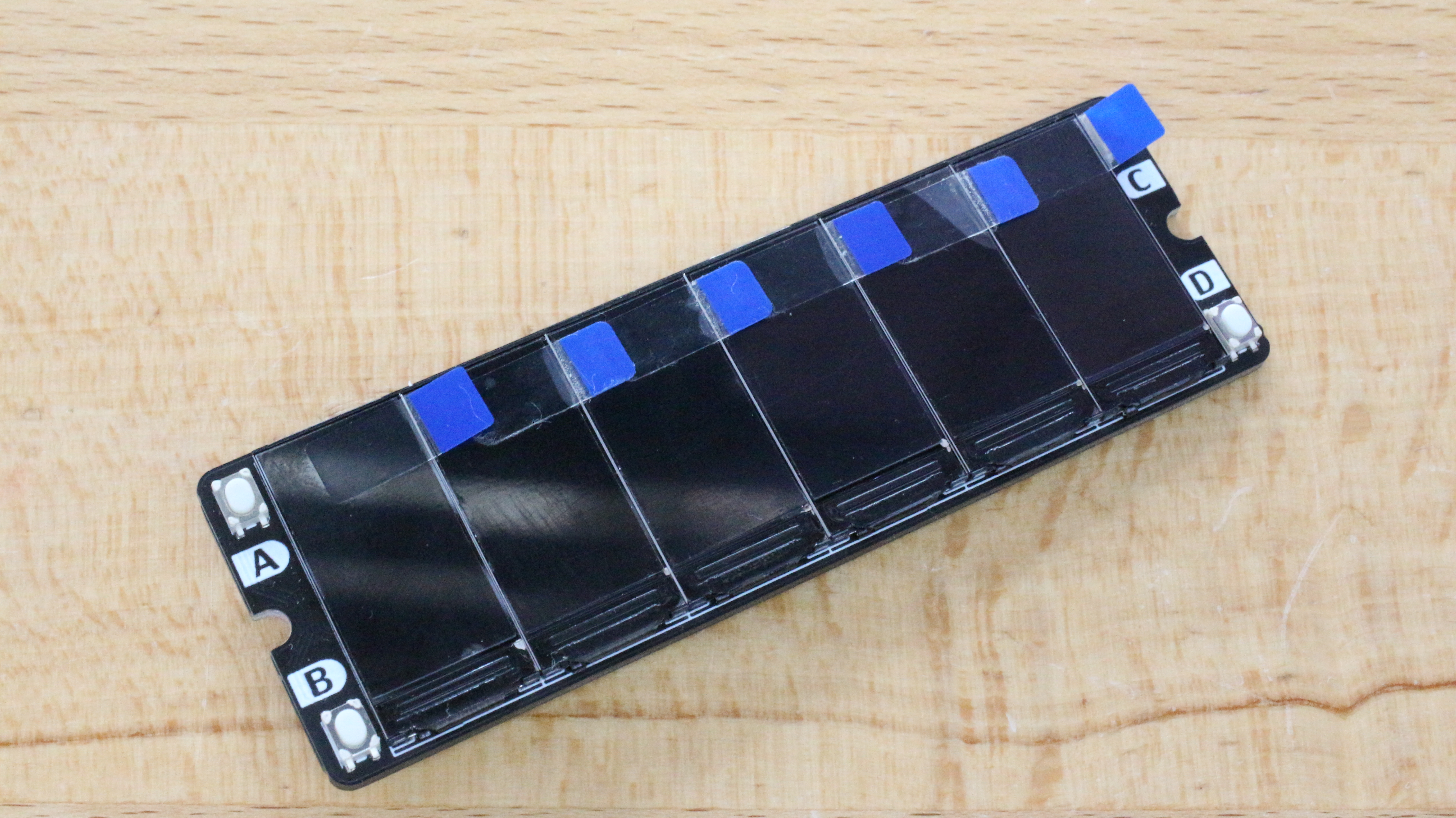
The PCB is intended to be compatible with any Microcontroller or SBC like the Raspberry as it only needs some GPIOs and an SPI Port. This makes the PCB compatible with a simple microcontroller as an Arduino to other more advanced microcontrollers. We could say this board is a breakout board for the arrangement of six displays and 4 buttons.
SPI Display Array Board CAD
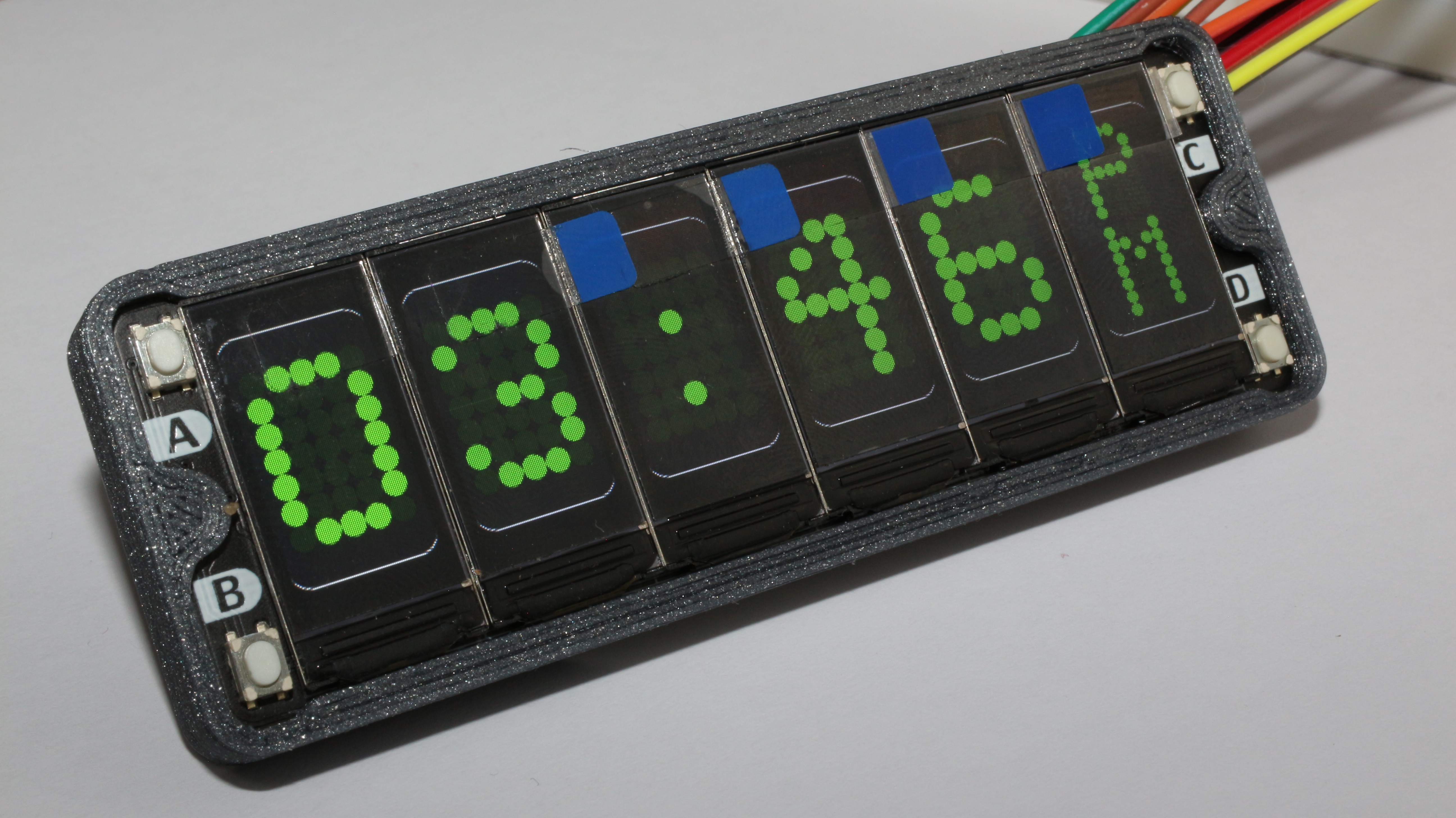
Testing the clock designs
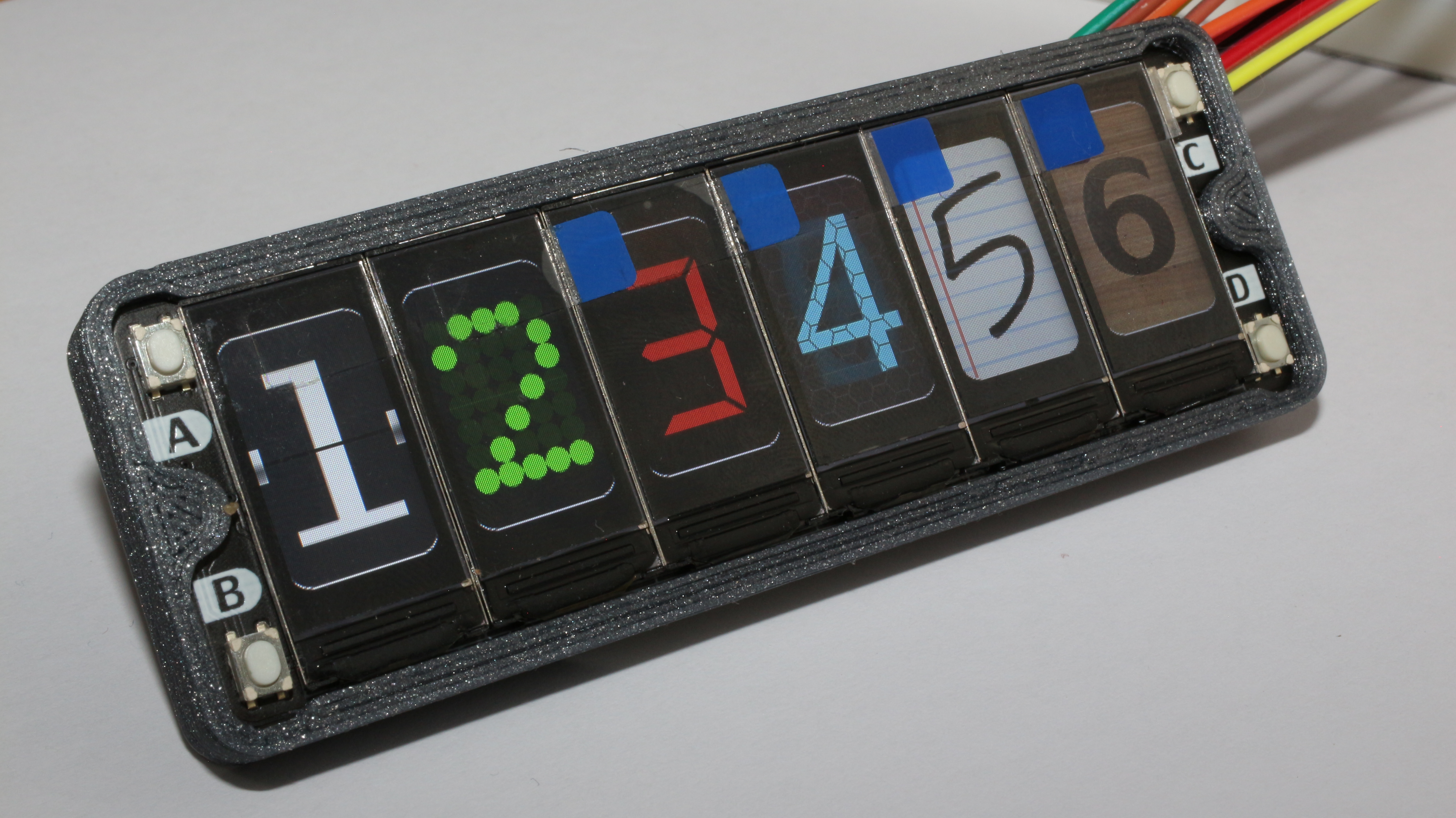
Before writing the clock firmware I decided to test all the designs that I have already created on the computer, so using the Raspberry Pi Pico I have written a simple program that allows me to set an image for each display in order to simulate how the clock would look like.
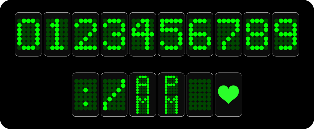
LED Matrix Clock
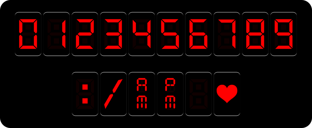
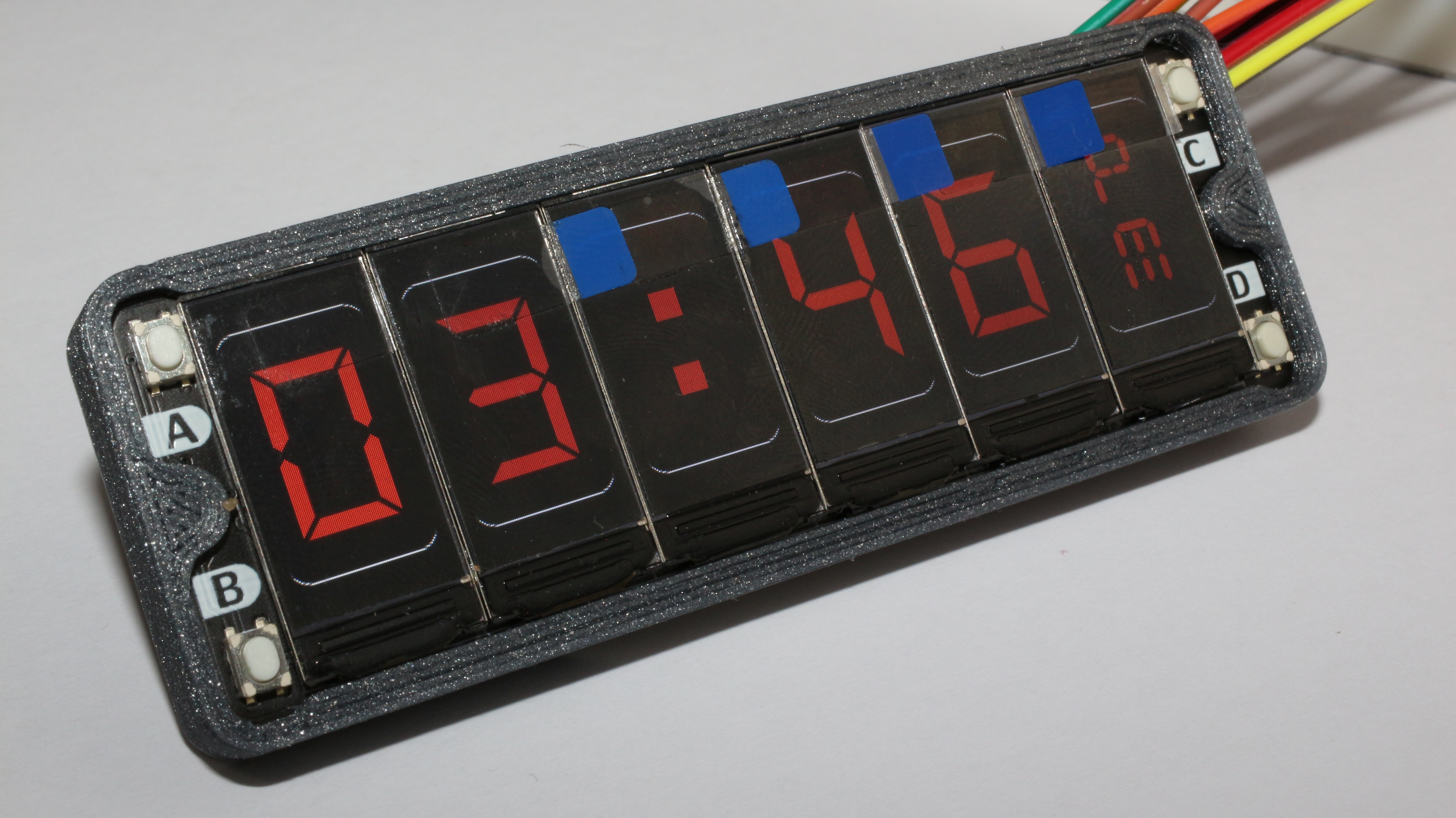
Digital Clock
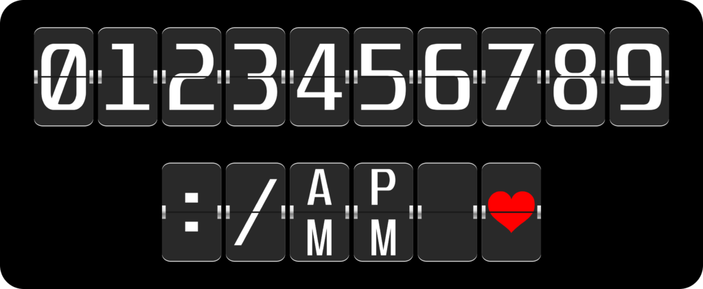
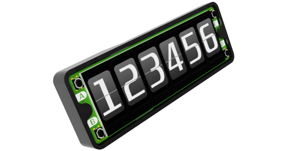
Flip Clock
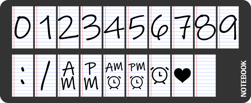
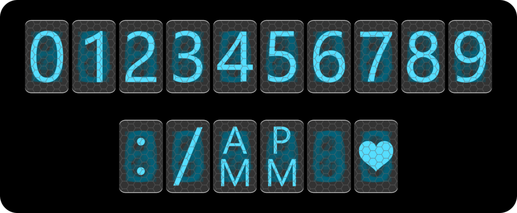
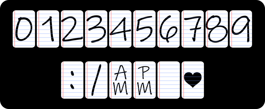
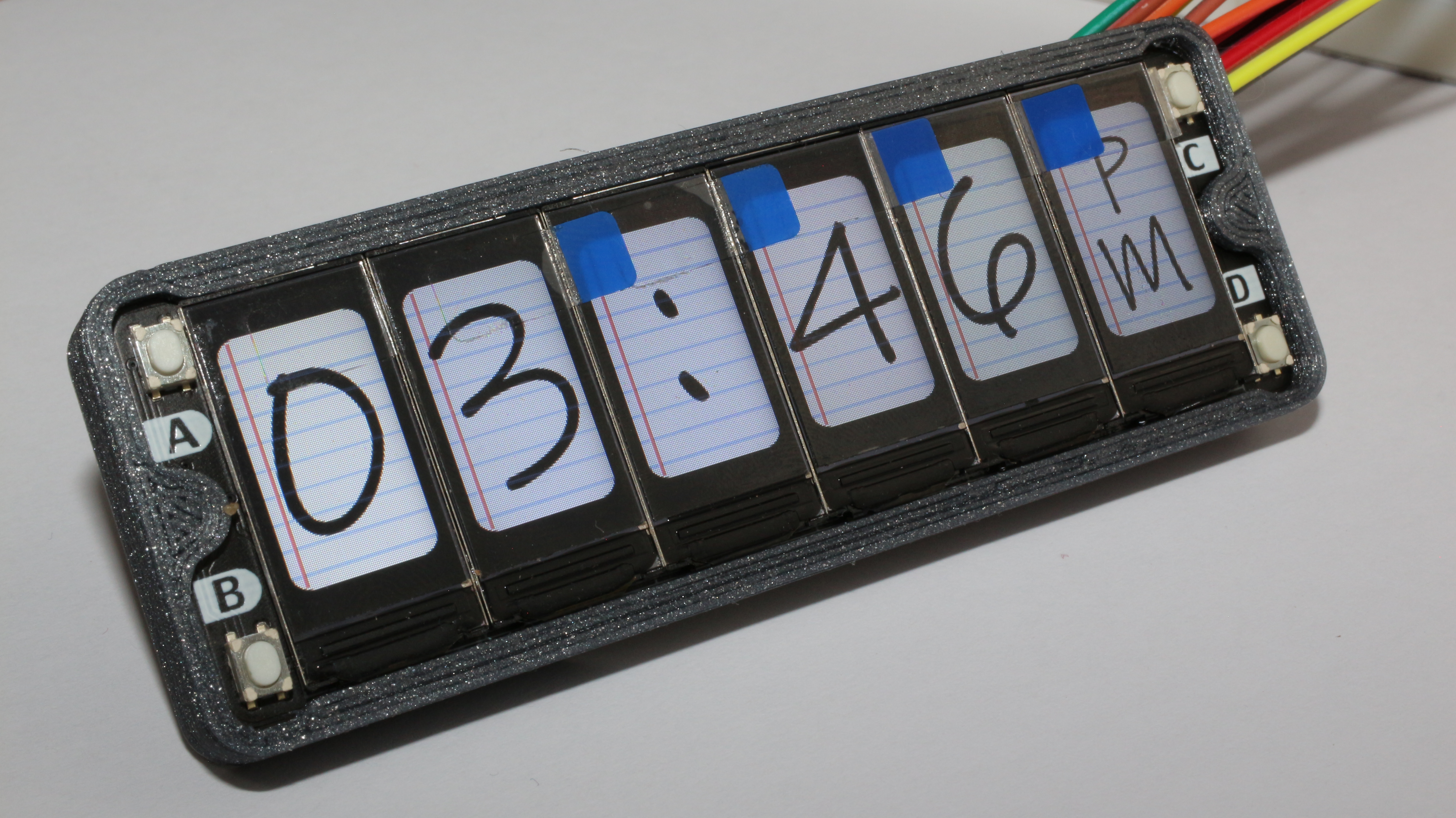
Ink Clock
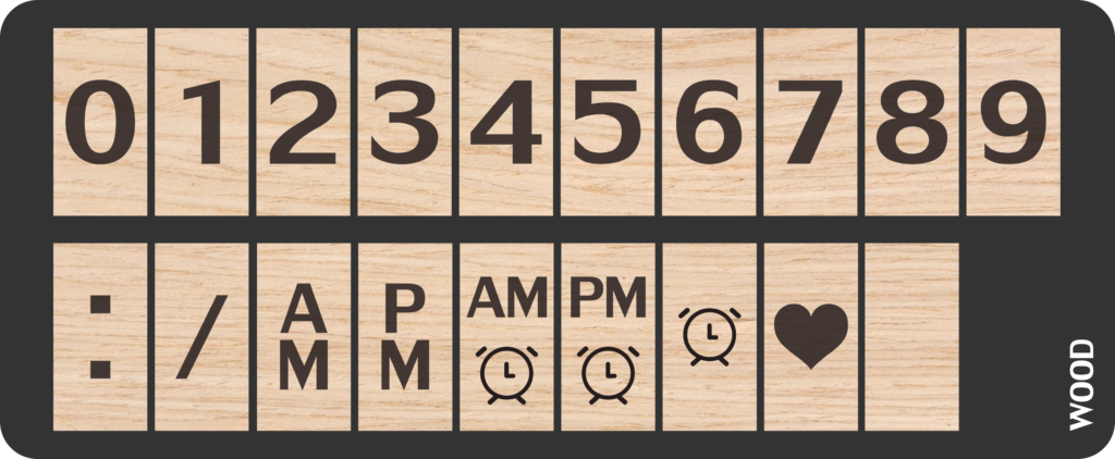
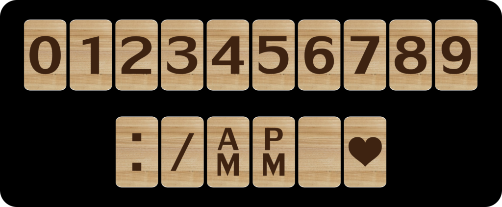
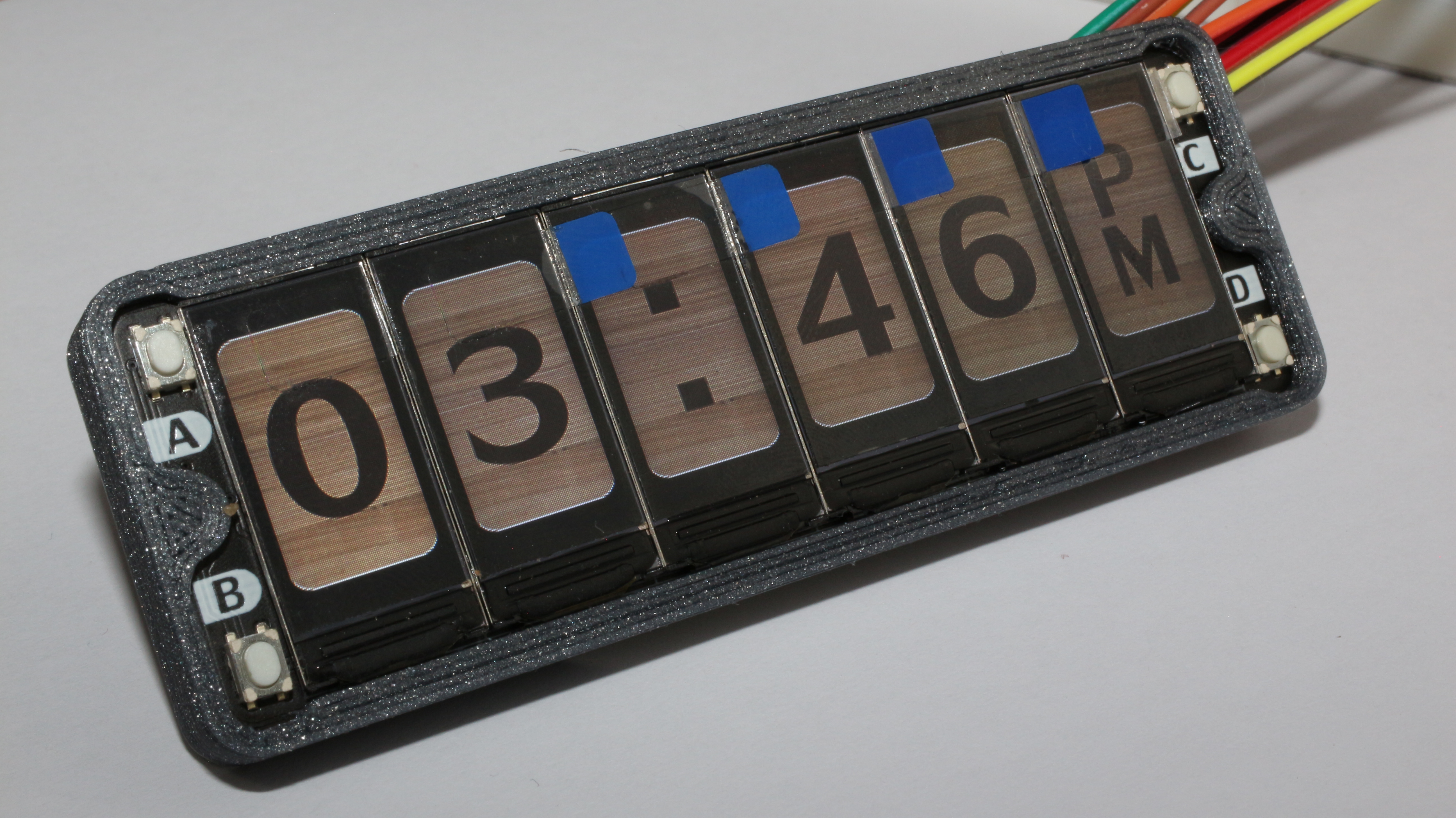
Wood Clock
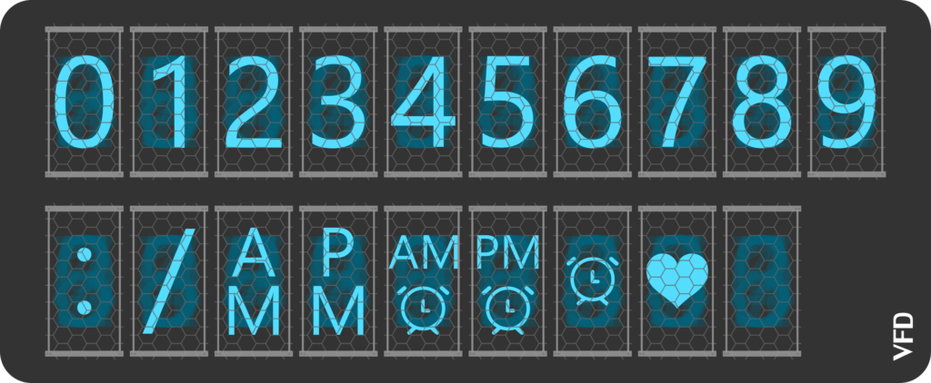
VFD Clock
Desing Test
The code for this simple task consists of the initialization of the displays and just sensing the raw data of each image to the corresponding display.
#include "pico/stdlib.h"
#include "hardware/gpio.h"
#include "hardware/pio.h"
#include "ST7735.h"

#include "clockDigital.h"
#include "clockFlip.h"
#include "clockMatrix.h"
#include "clockVFD.h"
#include "clockInk.h"
#include "clockWood.h"

#define ONBOARD_LED 25

int main(){
    stdio_init_all();

    PIO pio = pio0;
    uint sm = 0;
    uint offset = pio_add_program(pio, &SPILCD_program);
    lcdPIOInit(pio, sm, offset, PIN_SDI, PIN_SCK, SERIAL_CLK_DIV);


    gpio_init(ONBOARD_LED);
    gpio_set_dir(ONBOARD_LED, GPIO_OUT);

    gpio_init(PIN_CS1);
    gpio_init(PIN_CS2);
    gpio_init(PIN_CS3);
    gpio_init(PIN_CS4);
    gpio_init(PIN_CS5);
    gpio_init(PIN_CS6);
    gpio_init(PIN_DC);
    gpio_init(PIN_RST);
    gpio_init(PIN_BLK);

    gpio_set_dir(PIN_CS1, GPIO_OUT);
    gpio_set_dir(PIN_CS2, GPIO_OUT);
    gpio_set_dir(PIN_CS3, GPIO_OUT);
    gpio_set_dir(PIN_CS4, GPIO_OUT);
    gpio_set_dir(PIN_CS5, GPIO_OUT);
    gpio_set_dir(PIN_CS6, GPIO_OUT);
    gpio_set_dir(PIN_DC, GPIO_OUT);
    gpio_set_dir(PIN_RST, GPIO_OUT);
    gpio_set_dir(PIN_BLK, GPIO_OUT);

    gpio_put(ONBOARD_LED, 1);
    gpio_put(PIN_CS1, 0);
    gpio_put(PIN_CS2, 0);
    gpio_put(PIN_CS3, 0);
    gpio_put(PIN_CS4, 0);
    gpio_put(PIN_CS5, 0);
    gpio_put(PIN_CS6, 0);
    gpio_put(PIN_RST, 1);
    lcdInit(pio, sm, st7735_initSeq);
    gpio_put(PIN_BLK, 1);

    lcdStartPx(pio,sm);

    for (int i = 0; i < 160*80*2; i++){
       lcdPut(pio, sm, one_Flip[i]);
    }

    gpio_put(PIN_CS1, 1);
    for (int i = 0; i < 160*80*2; i++){
       lcdPut(pio, sm, two_Matrix[i]);
    }

    gpio_put(PIN_CS2, 1);
    for (int i = 0; i < 160*80*2; i++){
       lcdPut(pio, sm, three_Digital[i]);
    }

    gpio_put(PIN_CS3, 1);
    for (int i = 0; i < 160*80*2; i++){
       lcdPut(pio, sm, four_VFD[i]);
    }

    gpio_put(PIN_CS4, 1);
    for (int i = 0; i < 160*80*2; i++){
       lcdPut(pio, sm, five_Ink[i]);
    }

    gpio_put(PIN_CS5, 1);
    for (int i = 0; i < 160*80*2; i++){
       lcdPut(pio, sm, six_Wood[i]);
    }
}
The Raspberry Pi Pico is a very inexpensive microcontroller compared to other brands with ARM Cortex M0+ ( This one is a dual-core ), also has one special feature only found in more expensive microcontrollers like Cortex M4 it is the Raspberry PIO which is a way to create special hardware peripherals. In my Feather MK26F board, it is called FLEXBUS, and the equivalent can be found in other microcontrollers. So the remarkable feature for me of this microcontroller are:
XIP( Execute in place ) The ability to save and execute programs running on an external QUAD-SPI flash.
246Kb of RAM, that is a lot of RAM, mostly seen on mid-range microcontrollers.
133 Mhz Cortex M0+ dual-core
8 PIO, Programmable IO State machines.
USB-Bootloader with SWD debug capabilities.
Low price ( only $4 USD for the entire board ).
The Raspberry Pi PICO also has some bad things to take into account, and this is the lack of the reset button and a good IDE for the developing process. These features could come in the future as they are minor changes.
There are not many peripherals in this microcontroller but the PIO makes this even. it has 2 hardware SPI, 2 hardware UART, 2 hardware I2C, 3 12-bit ADC pins, 16 PWM channels, and Accelerated floating-point libraries on-chip ( We will see this in the example program below ).
I am not a fan of MicroPython or CircuitPython but it is nice to have in hand for a fast proof of concept. I like programming in C/C++ so I installed Visual Studio with the provided SDK.
The example that really grabbed my attention is the PIO ST7789, this example uses a custom peripheral with the PIO, making an impressive SPI with a baud rate of 60 Mbps and the use of the hardware interpolation libraries.