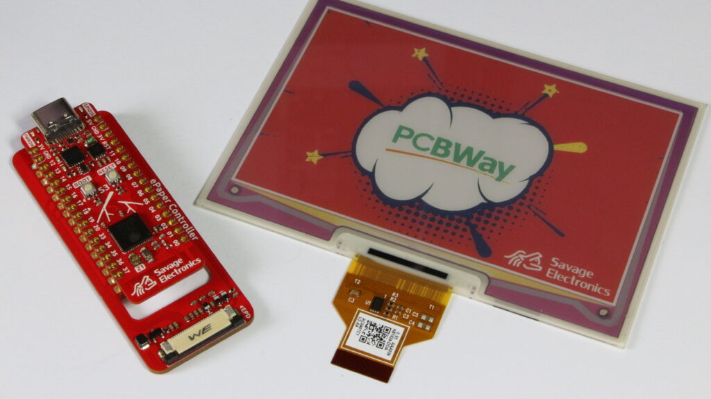
Sometimes there are projects that need more than one piece of the same PCB or it’s a design that is probably going to be used with other projects, that is the case for my ESP32-S3 Stick controller, as the ESP32-S3 is a very powerful and versatile microcontroller with Wifi and BLE and a lot of memory I am going to be using this PCB with many projects.
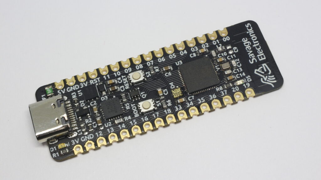
If you have been following my projects you will notice that it is pretty much the same development board as the ESP32-S2 Stick but now integrating the ESP32 S2 MCU and changing all the resistors, capacitors, and LEDs from 0603 to 0402 that makes a huge change for the PCB layout process.
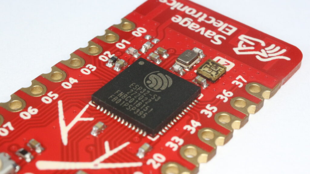
The ESP32-S3 is a dual-core XTensa LX7 MCU, capable of running at 240 MHz. Apart from its 512 KB of internal SRAM, it also comes with integrated 2.4 GHz, 802.11 b/g/n Wi-Fi, and Bluetooth 5 (LE) connectivity that provides long-range support. It has 45 programmable GPIOs and supports a rich set of peripherals.
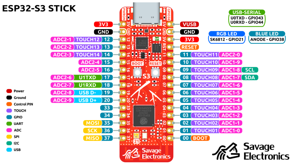
The ESP32-S3 Sticks incorporate some special features that I consider every ESP32 development board must have, such as a USB-Serial converter with RX and TX LEDs, a simple GPIO-LED, and an addressable RGB LED, at a second hand is always useful to have a reset and a general purpose push button.
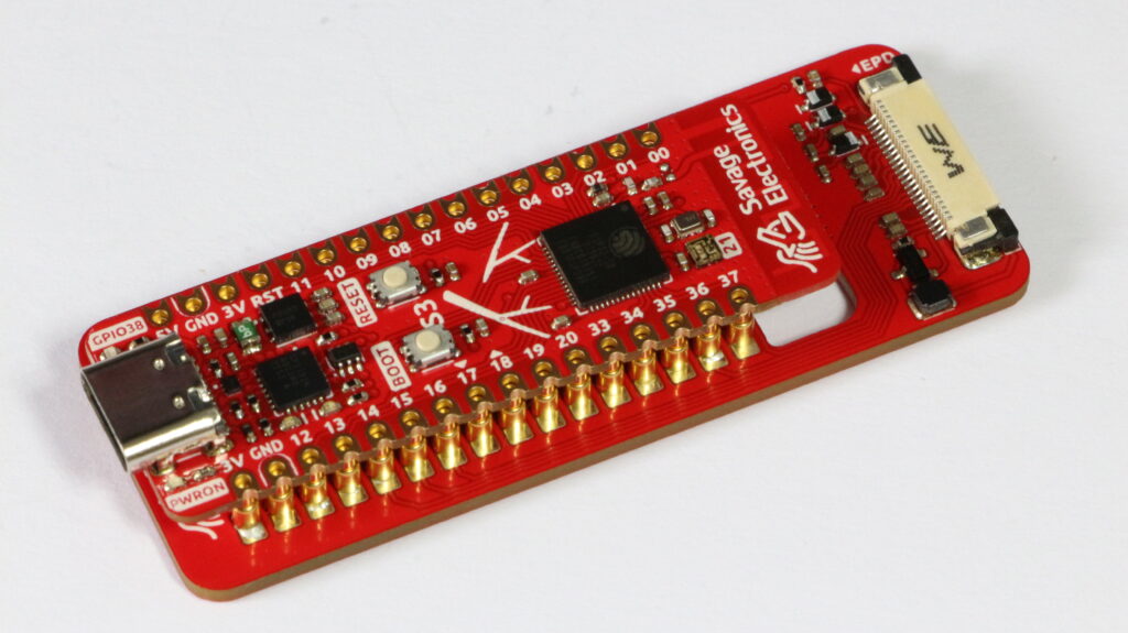
This board like many ESP32 boards is breadboard friendly for prototyping but it also has castellated pins that allow it to be soldered directly to other PCB like any other SMD component, so that makes it a very versatile board for rapid prototyping or development.
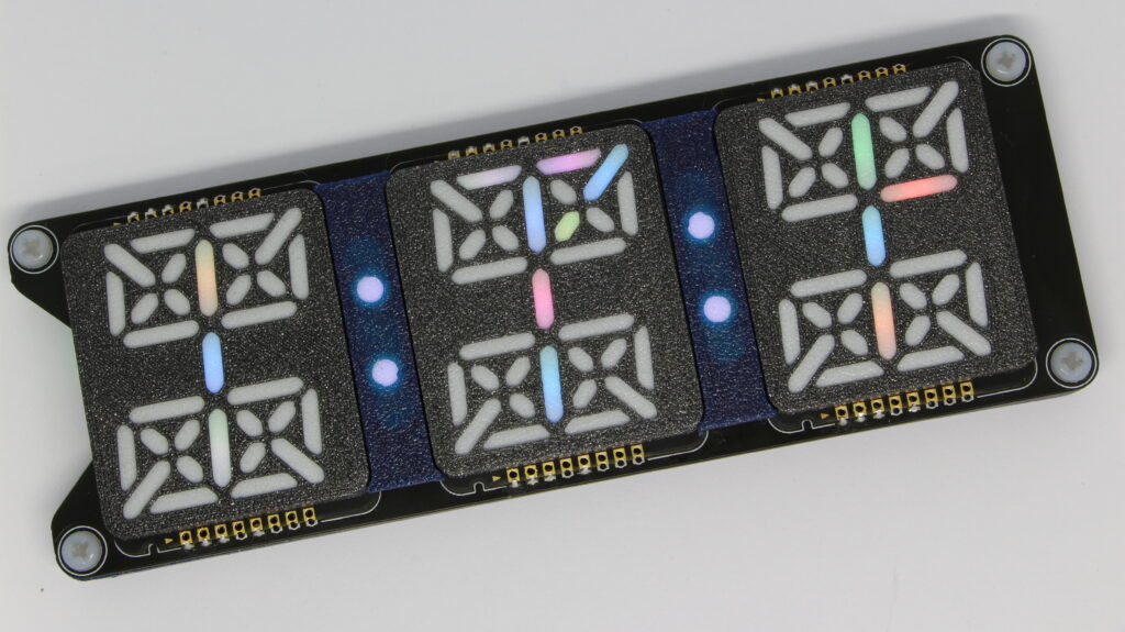
In order to test this new development board I have also designed a 7 Color Paper display driver that interconnects the Stick with a bed of Pogo-Pins that I bought from Aliexpress that are very easy to solder and fit the through-holes quite nicely.
I have really enjoyed working with the ESP32-S3 Stick and the Paper display, but I still have to think about a good final project for it, if you have any ideas you are welcome to leave them in the comments below.
All the files are available on my GitHub if you are interested in making one on your own or also if you want to make some improvements or specific application modifications.
After designing the nRF PRO I decided to continue using the form factor and add a more capable MCU as the ESP32-S2 that has Wifi capability with a lot of Memory for the app and data.
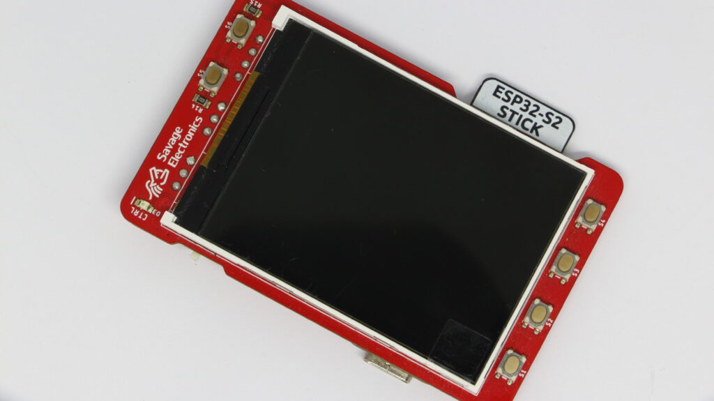
It is a breadboard-compatible development board featuring the ESP32-S2 series of SoC, Xtensa® single-core 32-bit LX7 microprocessor 4 MB flash and optional 2 MB PSRAM in chip package 26 GPIOs, rich set of peripherals such as UART, SPI, I2C, TOUCH, DAC, ADC, and USB, a 2x2mm SK6812 RGB serial LED and a 0603 SMD blue LED. USB-C connector, castellated holes for low-profile integrations, and an onboard PCB antenna.
ESP32-S2 Stick
I have been using this board for all my projects as it’s easier to add to all my current and old projects such as the display-Array, the Cistercian Display, and the Dynamixel Configurator.
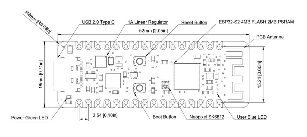
This board is very versatile as I have been able to use it easily to test any idea that I have in a protoboard before adding it to a custom PCB, also is easy to add to any new project and not having to place all of those components and having to RF match the antenna every single time. The dimensions are efficient and I love how it looks as it’s a very thin PCB.
ESP32-S2 Stick Dimensions
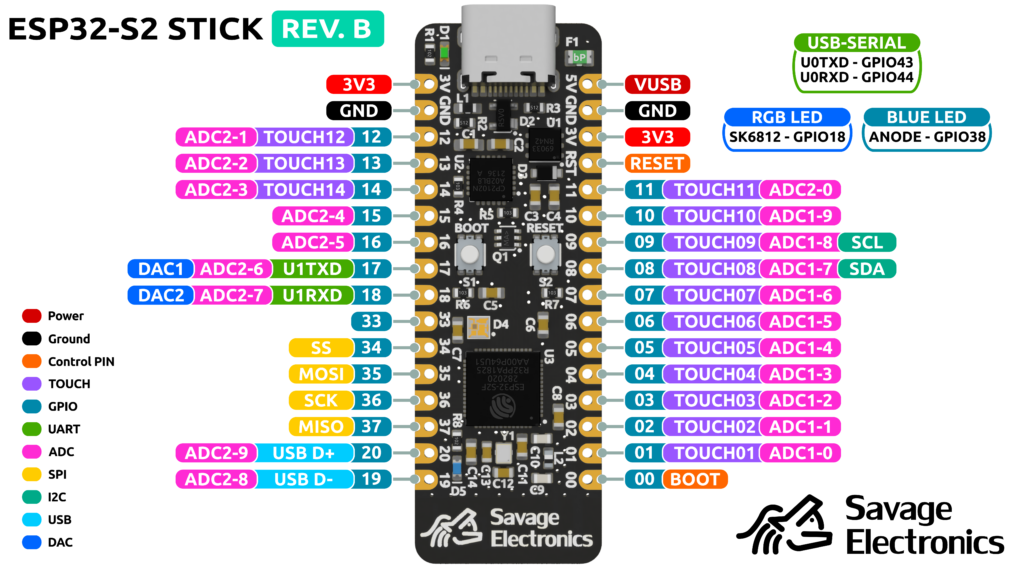
The board has enough pins with the correct peripheral in hand to accommodate to any project you may have.
ESP32-S2 Stick Pinout
Lately, I have been using the services ofPCBWayfor my projects as they have awesome customer support and great quality PCBs, I really love how they do the castellated holes for my boards in a couple of days.
ESP32-S2 Stick PanelESP32-S2 Stick Development board
Let me know in the comments below how would you use this board or any project idea that you would like me to explore using this board. If you need more detailed info go to my GitHub.
The Raspberry Pi Pico is a very capable microcontroller, good enough to drive the Display Array, easy to program, a lot of memory and speed but it does not have WiFi, That is why I have checked the ESP32 and it is also fast and with a lot of memory.
I have found that the ESP32-S2 is a nice option for the display array as it has a USB interface for the programming and not a real need for a USB-Serial converter, it has enough GPIOs even for an 8 display board.
I am very new with the ESP32 so I have tried with MicroPython, CircuitPython, Arduino, and Espressif repository running in Visual Studio Code, and the easiest for me was this last one, so I took the SNTP example located at the protocols example folder. In Visual Studio Code is the Espressif plug-in which makes it very easy and fast to get started with the ESP32.
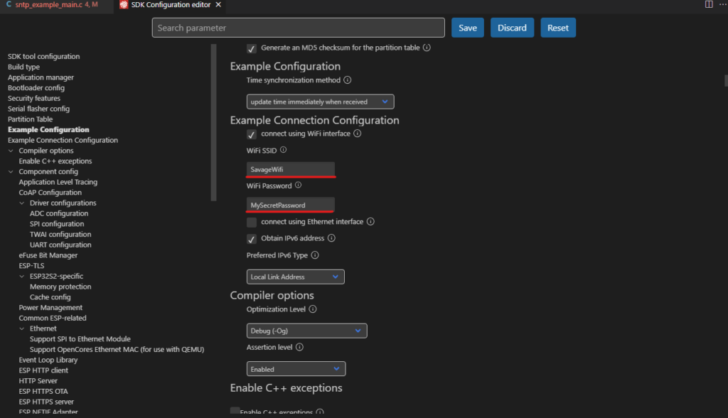
After installing and opening the example we just need to configure the example for the Wifi credentials.
And now is as easy as adding the SPI configurations for the displays.
/* LwIP SNTP example
This example code is in the Public Domain (or CC0 licensed, at your option.)
Unless required by applicable law or agreed to in writing, this
software is distributed on an "AS IS" BASIS, WITHOUT WARRANTIES OR
CONDITIONS OF ANY KIND, either express or implied.
*/
#include <string.h>
#include <time.h>
#include <sys/time.h>
#include "freertos/FreeRTOS.h"
#include "freertos/task.h"
#include "freertos/event_groups.h"
#include "esp_system.h"
#include "esp_event.h"
#include "esp_log.h"
#include "esp_attr.h"
#include "esp_sleep.h"
#include "nvs_flash.h"
#include "protocol_examples_common.h"
#include "esp_sntp.h"
//#include "clock14SEG.h"
#include "clockBINA.h"
//#include "clockDigital.h"
//#include "clockFlip.h"
//#include "clockInk.h"
#include "clockLixieCyan.h"
#include "clockLixiePurple.h"
//#include "clockMatrix.h"
#include "clockNIMO.h"
//#include "clockNixie.h"
//#include "clockVFD.h"
//#include "clockWood.h"
#include "clockFlags.h"
#define zero_Theme zero_BINA
#define one_Theme one_BINA
#define two_Theme two_BINA
#define three_Theme three_BINA
#define four_Theme four_BINA
#define five_Theme five_BINA
#define six_Theme six_BINA
#define seven_Theme seven_BINA
#define eight_Theme eight_BINA
#define nine_Theme nine_BINA
#define colon_Theme colon_BINA
#define space_Theme space_BINA
#define zero_Theme3 zero_LixiePurple
#define one_Theme3 one_LixiePurple
#define two_Theme3 two_LixiePurple
#define three_Theme3 three_LixiePurple
#define four_Theme3 four_LixiePurple
#define five_Theme3 five_LixiePurple
#define six_Theme3 six_LixiePurple
#define seven_Theme3 seven_LixiePurple
#define eight_Theme3 eight_LixiePurple
#define nine_Theme3 nine_LixiePurple
#define colon_Theme3 colon_LixiePurple
#define space_Theme3 space_LixiePurple
#define zero_Theme2 zero_LixieCyan
#define one_Theme2 one_LixieCyan
#define two_Theme2 two_LixieCyan
#define three_Theme2 three_LixieCyan
#define four_Theme2 four_LixieCyan
#define five_Theme2 five_LixieCyan
#define six_Theme2 six_LixieCyan
#define seven_Theme2 seven_LixieCyan
#define eight_Theme2 eight_LixieCyan
#define nine_Theme2 nine_LixieCyan
#define colon_Theme2 colon_LixieCyan
#define space_Theme2 space_LixieCyan
#define zero_Theme1 zero_NIMO
#define one_Theme1 one_NIMO
#define two_Theme1 two_NIMO
#define three_Theme1 three_NIMO
#define four_Theme1 four_NIMO
#define five_Theme1 five_NIMO
#define six_Theme1 six_NIMO
#define seven_Theme1 seven_NIMO
#define eight_Theme1 eight_NIMO
#define nine_Theme1 nine_NIMO
#define colon_Theme1 colon_NIMO
#define space_Theme1 space_NIMO
#define PIN_NUM_BLK 37
#define PIN_NUM_RST 33
#define PIN_NUM_DC 34
#define PIN_NUM_MOSI 35
#define PIN_NUM_CLK 36
#define PIN_NUM_MISO -1
#define PIN_NUM_CS1 1
#define PIN_NUM_CS2 2
#define PIN_NUM_CS3 3
#define PIN_NUM_CS4 4
#define PIN_NUM_CS5 5
#define PIN_NUM_CS6 6
#define PIN_NUM_BTA 10
#define PIN_NUM_BTB 11
#define PIN_NUM_BTC 12
#define PIN_NUM_BTD 13
#define PIN_NUM_BTE 0
/*
The LCD needs a bunch of command/argument values to be initialized. They are stored in this struct.
*/
typedef struct {
uint8_t cmd;
uint8_t data[16];
uint8_t databytes; //No of data in data; bit 7 = delay after set; 0xFF = end of cmds.
} lcd_init_cmd_t;
//Place data into DRAM. Constant data gets placed into DROM by default, which is not accessible by DMA.
DRAM_ATTR static const lcd_init_cmd_t st_init_cmds[]={
/* Sleep Out */
{0x11, {0}, 0x80},
/* Memory Data Access Control, MX=MV=1, MY=ML=MH=0, RGB=0 */
{0x36, {0xC8}, 1},
/* Interface Pixel Format, 16bits/pixel for RGB/MCU interface */
{0x3A, {0x05}, 1},
/* Porch Setting */
{0xB1, {0x01, 0x2C, 0x2D}, 3},
{0xB2, {0x01, 0x2C, 0x2D}, 3},
{0xB3, {0x01, 0x2C, 0x2D, 0x01, 0x2C, 0x2D}, 6},
{0xB4, {0x07}, 1},
/* LCM Control, XOR: BGR, MX, MH */
{0xC0, {0xA2,0x02,0x84}, 3},
{0xC1, {0xC5}, 1},
/* VDV and VRH Command Enable, enable=1 */
{0xC2, {0x0A, 0x00}, 2},
/* VRH Set, Vap=4.4+... */
{0xC3, {0x8A,0xEE}, 2},
/* VDV Set, VDV=0 */
{0xC5, {0x0E}, 1},
/* Column Address */
{0x2A, {0x00, 0x1A, 0x00, 0x69}, 4},
/* Row Address */
{0x2B, {0x00, 0x01, 0x00, 0xA0}, 4},
/* Positive Voltage Gamma Control */
{0xE0, {0x02, 0x1C, 0x07, 0x12, 0x37, 0x32, 0x29, 0x2D, 0x29, 0x25, 0x2B, 0x39, 0x00, 0x01, 0x03, 0x10}, 16},
/* Negative Voltage Gamma Control */
{0xE1, {0x03, 0x1D, 0x07, 0x06, 0x2E, 0x2C, 0x29, 0x2D, 0x2E, 0x2E, 0x37, 0x3F, 0x00, 0x00, 0x02, 0x10}, 16},
/* Inversion ON */
{0x21, {0}, 0x80},
/* Normal Display */
{0x13, {0}, 0x80},
/* Display On */
{0x29, {0}, 0x80},
/* Write Data */
{0x2C, {0}, 0x80},
{0, {0}, 0xff}
};
/* Send a command to the LCD. Uses spi_device_polling_transmit, which waits
* until the transfer is complete.
*
* Since command transactions are usually small, they are handled in polling
* mode for higher speed. The overhead of interrupt transactions is more than
* just waiting for the transaction to complete.
*/
void lcd_cmd(spi_device_handle_t spi, const uint8_t cmd)
{
esp_err_t ret;
spi_transaction_t t;
memset(&t, 0, sizeof(t)); //Zero out the transaction
t.length=8; //Command is 8 bits
t.tx_buffer=&cmd; //The data is the cmd itself
t.user=(void*)0; //D/C needs to be set to 0
ret=spi_device_polling_transmit(spi, &t); //Transmit!
assert(ret==ESP_OK); //Should have had no issues.
}
/* Send data to the LCD. Uses spi_device_polling_transmit, which waits until the
* transfer is complete.
*
* Since data transactions are usually small, they are handled in polling
* mode for higher speed. The overhead of interrupt transactions is more than
* just waiting for the transaction to complete.
*/
void lcd_data(spi_device_handle_t spi, const uint8_t *data, int len)
{
esp_err_t ret;
spi_transaction_t t;
if (len==0) return; //no need to send anything
memset(&t, 0, sizeof(t)); //Zero out the transaction
t.length=len*8; //Len is in bytes, transaction length is in bits.
t.tx_buffer=data; //Data
t.user=(void*)1; //D/C needs to be set to 1
ret=spi_device_polling_transmit(spi, &t); //Transmit!
assert(ret==ESP_OK); //Should have had no issues.
}
//This function is called (in irq context!) just before a transmission starts. It will
//set the D/C line to the value indicated in the user field.
void lcd_spi_pre_transfer_callback(spi_transaction_t *t){
int dc=(int)t->user;
gpio_set_level(PIN_NUM_DC, dc);
}
//Initialize the display
void lcd_init(spi_device_handle_t spi){
int cmd=0;
const lcd_init_cmd_t* lcd_init_cmds;
lcd_init_cmds = st_init_cmds;
//Initialize non-SPI GPIOs
gpio_set_direction(PIN_NUM_DC, GPIO_MODE_OUTPUT);
gpio_set_direction(PIN_NUM_RST, GPIO_MODE_OUTPUT);
gpio_set_direction(PIN_NUM_BLK, GPIO_MODE_OUTPUT);
gpio_set_direction(PIN_NUM_CS1, GPIO_MODE_OUTPUT);
gpio_set_direction(PIN_NUM_CS2, GPIO_MODE_OUTPUT);
gpio_set_direction(PIN_NUM_CS3, GPIO_MODE_OUTPUT);
gpio_set_direction(PIN_NUM_CS4, GPIO_MODE_OUTPUT);
gpio_set_direction(PIN_NUM_CS5, GPIO_MODE_OUTPUT);
gpio_set_direction(PIN_NUM_CS6, GPIO_MODE_OUTPUT);
gpio_set_direction(PIN_NUM_BTA, GPIO_MODE_INPUT);
gpio_set_direction(PIN_NUM_BTB, GPIO_MODE_INPUT);
gpio_set_direction(PIN_NUM_BTC, GPIO_MODE_INPUT);
gpio_set_direction(PIN_NUM_BTD, GPIO_MODE_INPUT);
gpio_set_direction(PIN_NUM_BTE, GPIO_MODE_INPUT);
gpio_set_level(PIN_NUM_CS1, 0);
gpio_set_level(PIN_NUM_CS2, 0);
gpio_set_level(PIN_NUM_CS3, 0);
gpio_set_level(PIN_NUM_CS4, 0);
gpio_set_level(PIN_NUM_CS5, 0);
gpio_set_level(PIN_NUM_CS6, 0);
gpio_set_level(PIN_NUM_BLK, 0);
//Reset the display
gpio_set_level(PIN_NUM_RST, 0);
vTaskDelay(100 / portTICK_RATE_MS);
gpio_set_level(PIN_NUM_RST, 1);
vTaskDelay(100 / portTICK_RATE_MS);
//Send all the commands
while (lcd_init_cmds[cmd].databytes!=0xff) {
lcd_cmd(spi, lcd_init_cmds[cmd].cmd);
lcd_data(spi, lcd_init_cmds[cmd].data, lcd_init_cmds[cmd].databytes&0x1F);
if (lcd_init_cmds[cmd].databytes&0x80) {
vTaskDelay(100 / portTICK_RATE_MS);
}
cmd++;
}
}
uint8_t clockTheme = 0;
uint8_t prevHours,prevMinutes,prevSeconds;
uint8_t imgBuffer[100];
uint8_t backlightStatus = 1;
uint8_t secondsCounter = 0;
uint8_t secondsStatus = 0;
void selectDisplay(uint8_t);
void lcdDrawNumber(spi_device_handle_t,uint8_t,uint8_t);
void lcdDrawFlag(spi_device_handle_t,uint8_t,uint8_t);
static void obtain_time(void);
static void initialize_sntp(void);
void app_main(void)
{
esp_err_t ret;
spi_device_handle_t spi;
spi_bus_config_t buscfg={
.miso_io_num=PIN_NUM_MISO,
.mosi_io_num=PIN_NUM_MOSI,
.sclk_io_num=PIN_NUM_CLK,
.quadwp_io_num=-1,
.quadhd_io_num=-1,
.max_transfer_sz=100
};
spi_device_interface_config_t devcfg={
.clock_speed_hz=40*1000*1000, //Clock out at 10 MHz
.mode=0, //SPI mode 0
//.spics_io_num=PIN_NUM_CS1, //CS pin
.queue_size=7, //We want to be able to queue 7 transactions at a time
.pre_cb=lcd_spi_pre_transfer_callback, //Specify pre-transfer callback to handle D/C line
};
//Initialize the SPI bus
ret=spi_bus_initialize(SPI2_HOST, &buscfg, SPI2_HOST);
ESP_ERROR_CHECK(ret);
//Attach the LCD to the SPI bus
ret=spi_bus_add_device(SPI2_HOST, &devcfg, &spi);
ESP_ERROR_CHECK(ret);
//Initialize the LCD
lcd_init(spi);
lcdDrawNumber(spi,0,11);
///Enable backlight
gpio_set_level(PIN_NUM_BLK, 1);
time_t now;
struct tm timeinfo;
time(&now);
localtime_r(&now, &timeinfo);
if (timeinfo.tm_year < (2016 - 1900)) { // Is time set? If not, tm_year will be (1970 - 1900).
obtain_time();
time(&now); // update 'now' variable with current time
}
// Set timezone to Mexico City Central Standard Time
setenv("TZ", "CST6CDT,M4.1.0/2,M10.5.0", 1); //EST5EDT,M3.2.0/2,M11.1.0
tzset();
localtime_r(&now, &timeinfo);
prevHours = 0;
prevMinutes = 0;
prevSeconds = 0;
lcdDrawFlag(spi,6,0);
while(1){
if(timeinfo.tm_hour != prevHours){
prevHours = timeinfo.tm_hour;
if(timeinfo.tm_hour < 10){
lcdDrawNumber(spi,1,0);
lcdDrawNumber(spi,2,timeinfo.tm_hour);
}else if (timeinfo.tm_hour < 20){
lcdDrawNumber(spi,1,1);
lcdDrawNumber(spi,2,timeinfo.tm_hour-10);
}else{
lcdDrawNumber(spi,1,2);
lcdDrawNumber(spi,2,timeinfo.tm_hour-20);
}
}
if(timeinfo.tm_min != prevMinutes){
prevMinutes = timeinfo.tm_min;
if(timeinfo.tm_min < 10){
lcdDrawNumber(spi,4,0);
lcdDrawNumber(spi,5,timeinfo.tm_min);
}else if (timeinfo.tm_min < 20){
lcdDrawNumber(spi,4,1);
lcdDrawNumber(spi,5,timeinfo.tm_min-10);
}else if (timeinfo.tm_min < 30){
lcdDrawNumber(spi,4,2);
lcdDrawNumber(spi,5,timeinfo.tm_min-20);
}else if (timeinfo.tm_min < 40){
lcdDrawNumber(spi,4,3);
lcdDrawNumber(spi,5,timeinfo.tm_min-30);
}else if (timeinfo.tm_min < 50){
lcdDrawNumber(spi,4,4);
lcdDrawNumber(spi,5,timeinfo.tm_min-40);
}else{
lcdDrawNumber(spi,4,5);
lcdDrawNumber(spi,5,timeinfo.tm_min-50);
}
}
vTaskDelay(20 / portTICK_PERIOD_MS);
secondsCounter++;
time(&now); // update 'now' variable with current time
localtime_r(&now, &timeinfo);
if(gpio_get_level(PIN_NUM_BTA) == 0){
clockTheme = 0;
setenv("TZ", "CST6CDT,M4.1.0/2,M10.5.0", 1); // Mexico City
tzset();
localtime_r(&now, &timeinfo);
prevHours = 0;
prevMinutes = 0;
prevSeconds = 0;
lcdDrawNumber(spi,1,0);
lcdDrawNumber(spi,2,0);
lcdDrawNumber(spi,4,0);
lcdDrawNumber(spi,5,0);
lcdDrawFlag(spi,6,0);
lcdDrawNumber(spi,3,10);
vTaskDelay(120 / portTICK_PERIOD_MS);
}
if(gpio_get_level(PIN_NUM_BTB) == 0){
clockTheme = 1;
setenv("TZ", "CET1CEST,M3.5.0/2,M10.5.0", 1); // Germany Berlin
tzset();
localtime_r(&now, &timeinfo);
prevHours = 0;
prevMinutes = 0;
prevSeconds = 0;
lcdDrawNumber(spi,1,0);
lcdDrawNumber(spi,2,0);
lcdDrawNumber(spi,4,0);
lcdDrawNumber(spi,5,0);
lcdDrawFlag(spi,6,1);
lcdDrawNumber(spi,3,10);
vTaskDelay(120 / portTICK_PERIOD_MS);
}
if(gpio_get_level(PIN_NUM_BTC) == 0){
clockTheme = 2;
setenv("TZ", "EST5EDT,M3.2.0/2,M11.1.0", 1); // USA New York
tzset();
localtime_r(&now, &timeinfo);
prevHours = 0;
prevMinutes = 0;
prevSeconds = 0;
lcdDrawNumber(spi,1,0);
lcdDrawNumber(spi,2,0);
lcdDrawNumber(spi,4,0);
lcdDrawNumber(spi,5,0);
lcdDrawFlag(spi,6,2);
lcdDrawNumber(spi,3,10);
vTaskDelay(120 / portTICK_PERIOD_MS);
}
if (gpio_get_level(PIN_NUM_BTD) == 0){
clockTheme = 3;
setenv("TZ", "GMT0BST,M3.5.0/2,M10.5.0", 1); // UK London
tzset();
localtime_r(&now, &timeinfo);
prevHours = 0;
prevMinutes = 0;
prevSeconds = 0;
lcdDrawNumber(spi,1,0);
lcdDrawNumber(spi,2,0);
lcdDrawNumber(spi,4,0);
lcdDrawNumber(spi,5,0);
lcdDrawFlag(spi,6,3);
lcdDrawNumber(spi,3,10);
vTaskDelay(120 / portTICK_PERIOD_MS);
}
if((secondsCounter > 25) & (secondsStatus == 0)){
lcdDrawNumber(spi,3,10);
secondsStatus = 1;
secondsCounter = 0;
} else if((secondsCounter > 25) & (secondsStatus == 1)){
lcdDrawNumber(spi,3,11);
secondsStatus = 0;
secondsCounter = 0;
}
if((gpio_get_level(PIN_NUM_BTE) == 0) & (backlightStatus == 1)){
backlightStatus = 0;
gpio_set_level(PIN_NUM_BLK, 0);
vTaskDelay(120 / portTICK_PERIOD_MS);
} else if((gpio_get_level(PIN_NUM_BTE) == 0) & (backlightStatus == 0)){
backlightStatus = 1;
gpio_set_level(PIN_NUM_BLK, 1);
vTaskDelay(120 / portTICK_PERIOD_MS);
}
}
}
static void obtain_time(void){
ESP_ERROR_CHECK( nvs_flash_init() );
ESP_ERROR_CHECK(esp_netif_init());
ESP_ERROR_CHECK( esp_event_loop_create_default() );
/* This helper function configures Wi-Fi or Ethernet, as selected in menuconfig.
* Read "Establishing Wi-Fi or Ethernet Connection" section in
* examples/protocols/README.md for more information about this function.
*/
ESP_ERROR_CHECK(example_connect());
initialize_sntp();
time_t now = 0; // wait for time to be set
struct tm timeinfo = { 0 };
int retry = 0;
const int retry_count = 10;
while (sntp_get_sync_status() == SNTP_SYNC_STATUS_RESET && ++retry < retry_count) {
vTaskDelay(2000 / portTICK_PERIOD_MS);}
time(&now);
localtime_r(&now, &timeinfo);
ESP_ERROR_CHECK( example_disconnect() );
}
static void initialize_sntp(void){
sntp_setoperatingmode(SNTP_OPMODE_POLL);
sntp_setservername(0, "pool.ntp.org");
sntp_init();
}
void selectDisplay(uint8_t display){
switch(display){
case 0:
gpio_set_level(PIN_NUM_CS1, 0);
gpio_set_level(PIN_NUM_CS2, 0);
gpio_set_level(PIN_NUM_CS3, 0);
gpio_set_level(PIN_NUM_CS4, 0);
gpio_set_level(PIN_NUM_CS5, 0);
gpio_set_level(PIN_NUM_CS6, 0);
break;
case 1:
gpio_set_level(PIN_NUM_CS1, 0);
gpio_set_level(PIN_NUM_CS2, 1);
gpio_set_level(PIN_NUM_CS3, 1);
gpio_set_level(PIN_NUM_CS4, 1);
gpio_set_level(PIN_NUM_CS5, 1);
gpio_set_level(PIN_NUM_CS6, 1);
break;
case 2:
gpio_set_level(PIN_NUM_CS1, 1);
gpio_set_level(PIN_NUM_CS2, 0);
gpio_set_level(PIN_NUM_CS3, 1);
gpio_set_level(PIN_NUM_CS4, 1);
gpio_set_level(PIN_NUM_CS5, 1);
gpio_set_level(PIN_NUM_CS6, 1);
break;
case 3:
gpio_set_level(PIN_NUM_CS1, 1);
gpio_set_level(PIN_NUM_CS2, 1);
gpio_set_level(PIN_NUM_CS3, 0);
gpio_set_level(PIN_NUM_CS4, 1);
gpio_set_level(PIN_NUM_CS5, 1);
gpio_set_level(PIN_NUM_CS6, 1);
break;
case 4:
gpio_set_level(PIN_NUM_CS1, 1);
gpio_set_level(PIN_NUM_CS2, 1);
gpio_set_level(PIN_NUM_CS3, 1);
gpio_set_level(PIN_NUM_CS4, 0);
gpio_set_level(PIN_NUM_CS5, 1);
gpio_set_level(PIN_NUM_CS6, 1);
break;
case 5:
gpio_set_level(PIN_NUM_CS1, 1);
gpio_set_level(PIN_NUM_CS2, 1);
gpio_set_level(PIN_NUM_CS3, 1);
gpio_set_level(PIN_NUM_CS4, 1);
gpio_set_level(PIN_NUM_CS5, 0);
gpio_set_level(PIN_NUM_CS6, 1);
break;
case 6:
gpio_set_level(PIN_NUM_CS1, 1);
gpio_set_level(PIN_NUM_CS2, 1);
gpio_set_level(PIN_NUM_CS3, 1);
gpio_set_level(PIN_NUM_CS4, 1);
gpio_set_level(PIN_NUM_CS5, 1);
gpio_set_level(PIN_NUM_CS6, 0);
break;
case 9:
gpio_set_level(PIN_NUM_CS1, 0);
gpio_set_level(PIN_NUM_CS2, 0);
gpio_set_level(PIN_NUM_CS3, 0);
gpio_set_level(PIN_NUM_CS4, 0);
gpio_set_level(PIN_NUM_CS5, 0);
gpio_set_level(PIN_NUM_CS6, 0);
break;
default:
gpio_set_level(PIN_NUM_CS1, 1);
gpio_set_level(PIN_NUM_CS2, 1);
gpio_set_level(PIN_NUM_CS3, 1);
gpio_set_level(PIN_NUM_CS4, 1);
gpio_set_level(PIN_NUM_CS5, 1);
gpio_set_level(PIN_NUM_CS6, 1);
break;
}
}
void lcdDrawNumber(spi_device_handle_t spi, uint8_t Display, uint8_t Number){
selectDisplay(Display);
switch(Number){
case 0:
for(int k = 0; k < 256; k++){
for(int j = 0; j < 100; j++){
if(clockTheme == 0)
imgBuffer[j] = zero_Theme[j+(100*k)];
else if (clockTheme == 1)
imgBuffer[j] = zero_Theme1[j+(100*k)];
else if (clockTheme == 2)
imgBuffer[j] = zero_Theme2[j+(100*k)];
else if (clockTheme == 3)
imgBuffer[j] = zero_Theme3[j+(100*k)];
}
lcd_data(spi, imgBuffer,100);
}
break;
case 1:
for(int k = 0; k < 256; k++){
for(int j = 0; j < 100; j++){
if(clockTheme == 0)
imgBuffer[j] = one_Theme[j+(100*k)];
else if (clockTheme == 1)
imgBuffer[j] = one_Theme1[j+(100*k)];
else if (clockTheme == 2)
imgBuffer[j] = one_Theme2[j+(100*k)];
else if (clockTheme == 3)
imgBuffer[j] = one_Theme3[j+(100*k)];
}
lcd_data(spi, imgBuffer,100);
}
break;
case 2:
for(int k = 0; k < 256; k++){
for(int j = 0; j < 100; j++){
if(clockTheme == 0)
imgBuffer[j] = two_Theme[j+(100*k)];
else if (clockTheme == 1)
imgBuffer[j] = two_Theme1[j+(100*k)];
else if (clockTheme == 2)
imgBuffer[j] = two_Theme2[j+(100*k)];
else if (clockTheme == 3)
imgBuffer[j] = two_Theme3[j+(100*k)];
}
lcd_data(spi, imgBuffer,100);
}
break;
case 3:
for(int k = 0; k < 256; k++){
for(int j = 0; j < 100; j++){
if(clockTheme == 0)
imgBuffer[j] = three_Theme[j+(100*k)];
else if (clockTheme == 1)
imgBuffer[j] = three_Theme1[j+(100*k)];
else if (clockTheme == 2)
imgBuffer[j] = three_Theme2[j+(100*k)];
else if (clockTheme == 3)
imgBuffer[j] = three_Theme3[j+(100*k)];
}
lcd_data(spi, imgBuffer,100);
}
break;
case 4:
for(int k = 0; k < 256; k++){
for(int j = 0; j < 100; j++){
if(clockTheme == 0)
imgBuffer[j] = four_Theme[j+(100*k)];
else if (clockTheme == 1)
imgBuffer[j] = four_Theme1[j+(100*k)];
else if (clockTheme == 2)
imgBuffer[j] = four_Theme2[j+(100*k)];
else if (clockTheme == 3)
imgBuffer[j] = four_Theme3[j+(100*k)];
}
lcd_data(spi, imgBuffer,100);
}
break;
case 5:
for(int k = 0; k < 256; k++){
for(int j = 0; j < 100; j++){
if(clockTheme == 0)
imgBuffer[j] = five_Theme[j+(100*k)];
else if (clockTheme == 1)
imgBuffer[j] = five_Theme1[j+(100*k)];
else if (clockTheme == 2)
imgBuffer[j] = five_Theme2[j+(100*k)];
else if (clockTheme == 3)
imgBuffer[j] = five_Theme3[j+(100*k)];
}
lcd_data(spi, imgBuffer,100);
}
break;
case 6:
for(int k = 0; k < 256; k++){
for(int j = 0; j < 100; j++){
if(clockTheme == 0)
imgBuffer[j] = six_Theme[j+(100*k)];
else if (clockTheme == 1)
imgBuffer[j] = six_Theme1[j+(100*k)];
else if (clockTheme == 2)
imgBuffer[j] = six_Theme2[j+(100*k)];
else if (clockTheme == 3)
imgBuffer[j] = six_Theme3[j+(100*k)];
}
lcd_data(spi, imgBuffer,100);
}
break;
case 7:
for(int k = 0; k < 256; k++){
for(int j = 0; j < 100; j++){
if(clockTheme == 0)
imgBuffer[j] = seven_Theme[j+(100*k)];
else if (clockTheme == 1)
imgBuffer[j] = seven_Theme1[j+(100*k)];
else if (clockTheme == 2)
imgBuffer[j] = seven_Theme2[j+(100*k)];
else if (clockTheme == 3)
imgBuffer[j] = seven_Theme3[j+(100*k)];
}
lcd_data(spi, imgBuffer,100);
}
break;
case 8:
for(int k = 0; k < 256; k++){
for(int j = 0; j < 100; j++){
if(clockTheme == 0)
imgBuffer[j] = eight_Theme[j+(100*k)];
else if (clockTheme == 1)
imgBuffer[j] = eight_Theme1[j+(100*k)];
else if (clockTheme == 2)
imgBuffer[j] = eight_Theme2[j+(100*k)];
else if (clockTheme == 3)
imgBuffer[j] = eight_Theme3[j+(100*k)];
}
lcd_data(spi, imgBuffer,100);
}
break;
case 9:
for(int k = 0; k < 256; k++){
for(int j = 0; j < 100; j++){
if(clockTheme == 0)
imgBuffer[j] = nine_Theme[j+(100*k)];
else if (clockTheme == 1)
imgBuffer[j] = nine_Theme1[j+(100*k)];
else if (clockTheme == 2)
imgBuffer[j] = nine_Theme2[j+(100*k)];
else if (clockTheme == 3)
imgBuffer[j] = nine_Theme3[j+(100*k)];
}
lcd_data(spi, imgBuffer,100);
}
break;
case 10:
for(int k = 0; k < 256; k++){
for(int j = 0; j < 100; j++){
if(clockTheme == 0)
imgBuffer[j] = colon_Theme[j+(100*k)];
else if (clockTheme == 1)
imgBuffer[j] = colon_Theme1[j+(100*k)];
else if (clockTheme == 2)
imgBuffer[j] = colon_Theme2[j+(100*k)];
else if (clockTheme == 3)
imgBuffer[j] = colon_Theme3[j+(100*k)];
}
lcd_data(spi, imgBuffer,100);
}
break;
case 11:
for(int k = 0; k < 256; k++){
for(int j = 0; j < 100; j++){
if(clockTheme == 0)
imgBuffer[j] = space_Theme[j+(100*k)];
else if (clockTheme == 1)
imgBuffer[j] = space_Theme1[j+(100*k)];
else if (clockTheme == 2)
imgBuffer[j] = space_Theme2[j+(100*k)];
else if (clockTheme == 3)
imgBuffer[j] = space_Theme3[j+(100*k)];
}
lcd_data(spi, imgBuffer,100);
}
break;
}
}
void lcdDrawFlag(spi_device_handle_t spi, uint8_t Display, uint8_t Flag){
selectDisplay(Display);
switch (Flag){
case 0:
for(int k = 0; k < 256; k++){
for(int j = 0; j < 100; j++){
imgBuffer[j] = mex_Flag[j+(100*k)];
}
lcd_data(spi, imgBuffer,100);
}
break;
case 1:
for(int k = 0; k < 256; k++){
for(int j = 0; j < 100; j++){
imgBuffer[j] = deu_Flag[j+(100*k)];
}
lcd_data(spi, imgBuffer,100);
}
break;
case 2:
for(int k = 0; k < 256; k++){
for(int j = 0; j < 100; j++){
imgBuffer[j] = usa_Flag[j+(100*k)];
}
lcd_data(spi, imgBuffer,100);
}
break;
case 3:
for(int k = 0; k < 256; k++){
for(int j = 0; j < 100; j++){
imgBuffer[j] = gbr_Flag[j+(100*k)];
}
lcd_data(spi, imgBuffer,100);
}
break;
}
}
For this new firmware version, I have drawn some flags to set different time zones available with the A, B, C, and D buttons.
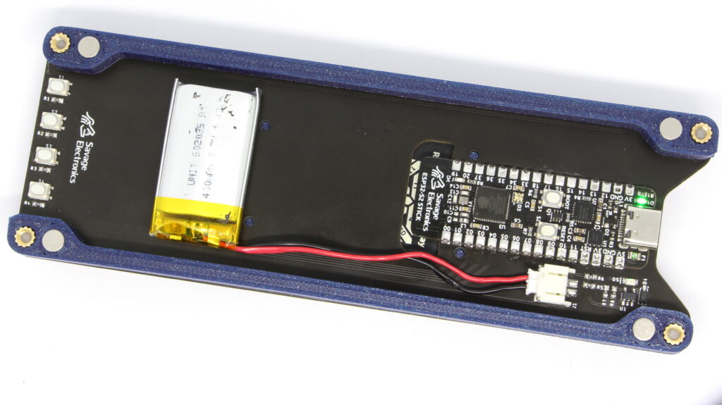
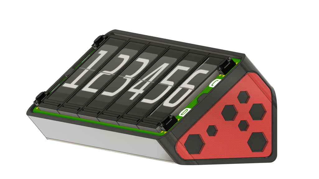
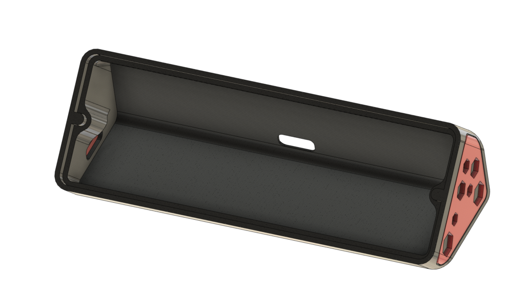
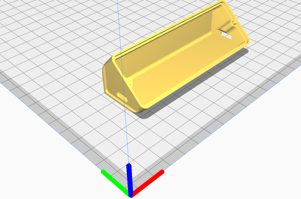
After having the code ready and tested It is time to design a case for it. I am also a newbie in 3D design but this is what I manage to design.
This case makes it possible to add your own controller board and USB power to one side or at the back of the case. I will also make available the 3D design file ( Fusion 360 ). These files can be printed without any supports if you want, but maybe the main case will need a few of them.