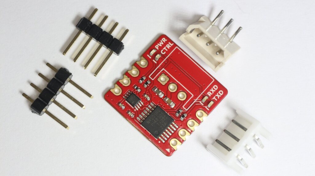
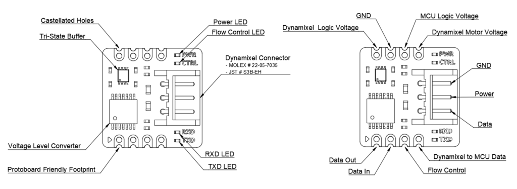
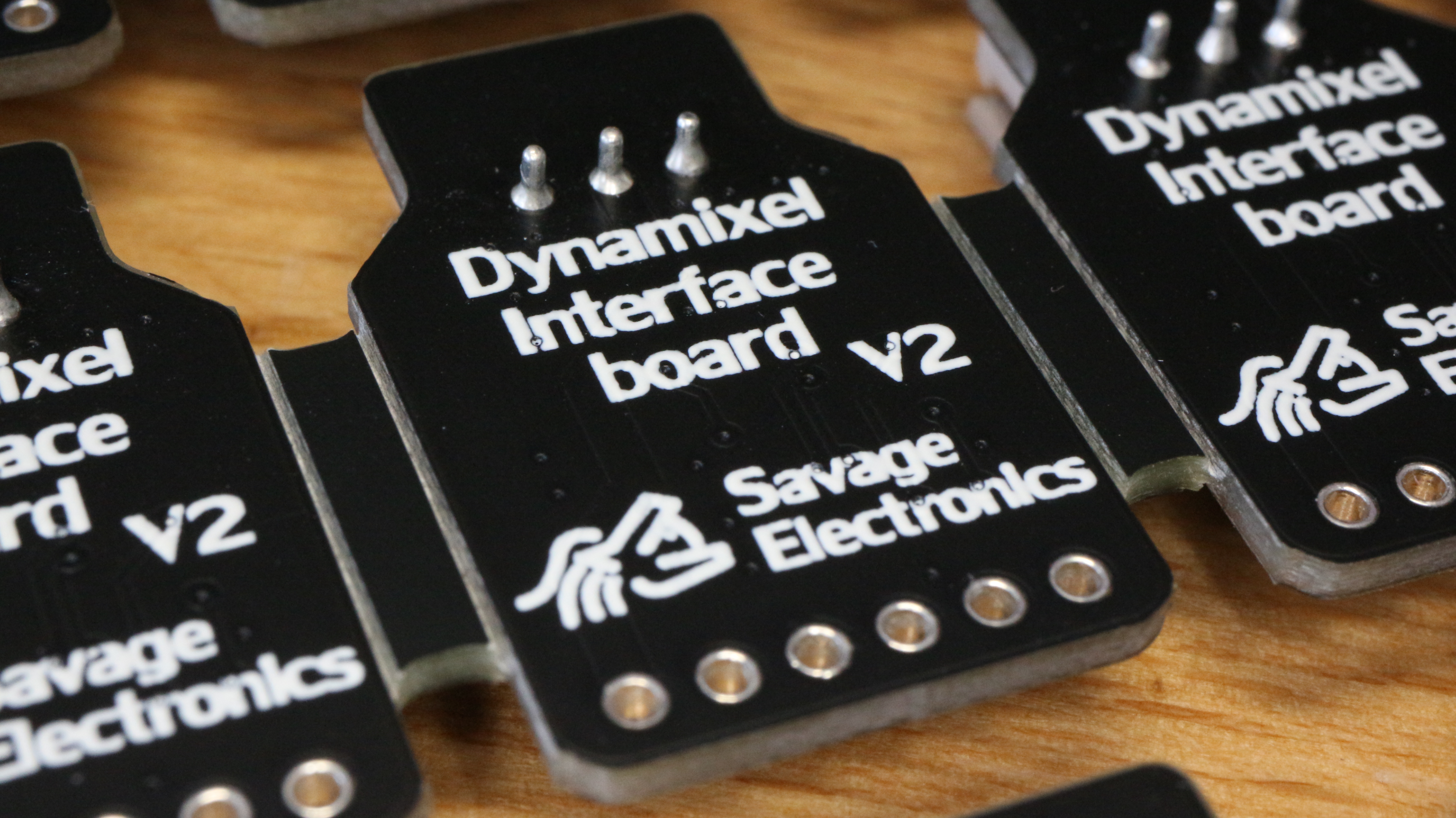
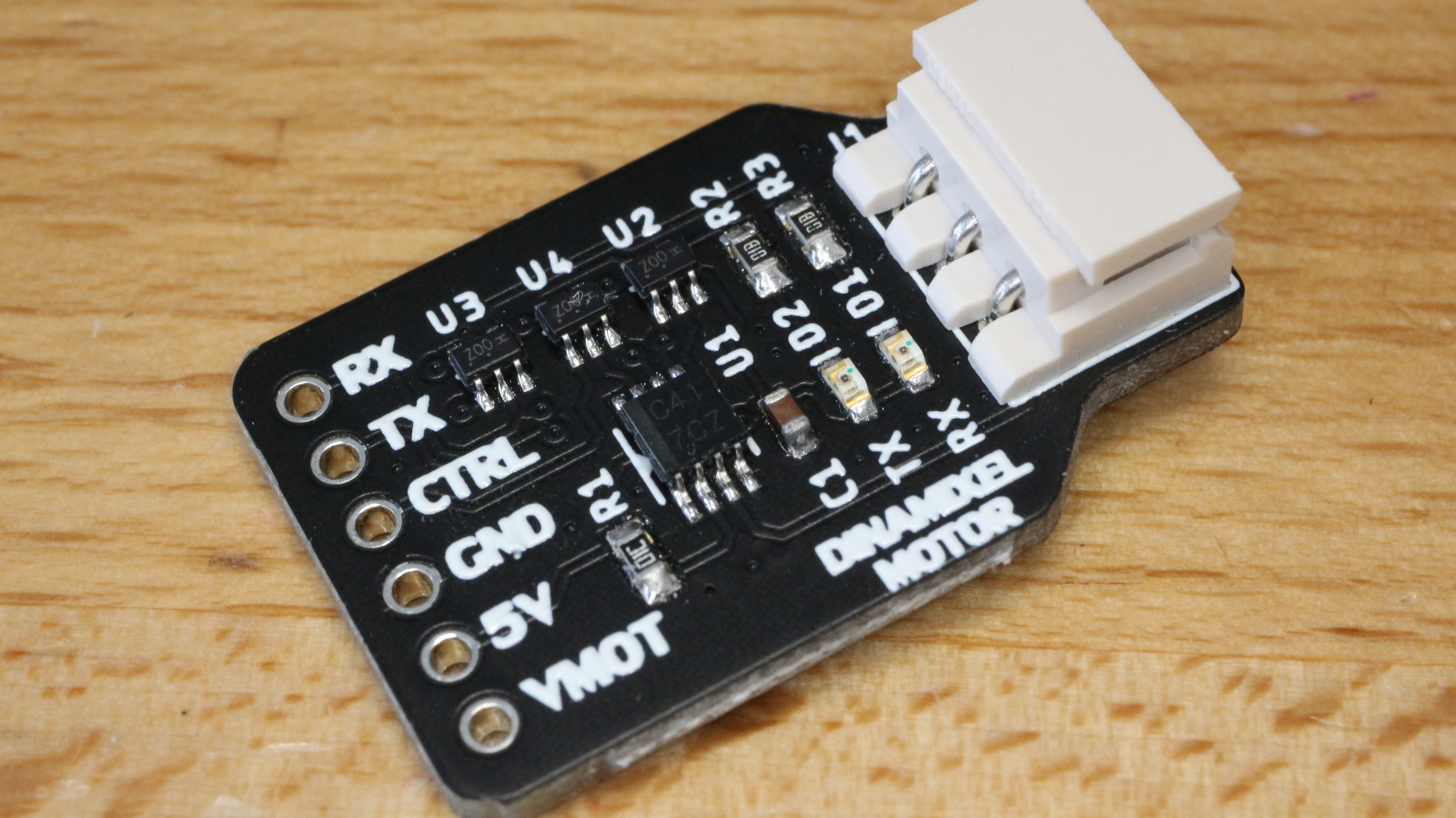
The Dynamixel Interface is a board that allows easy communication with a MCU or Processor with a simple UART module, the board integrates a voltage level converter and a Tri-state buffer to accomplish good communication between a Dynamixel servomotor and almost any microcontroller in the market. The board is breadboard-friendly and development ready as the connection pins are 0.1″ standard pitch and the castellated holes for SMD mounting and manufactured by PCBWay.
The Dynamixel interface is now easier to connect with a bunch of microcontrollers thanks to its voltage converter IC which makes possible the communication with low-power MCUs or even FPGAs, the interface offers communication indications LED for RX and TX, as well for the flow communication pin.
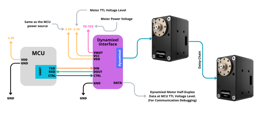
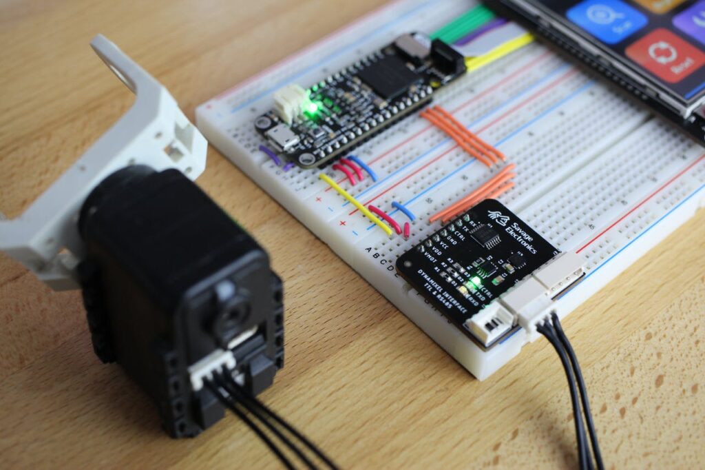
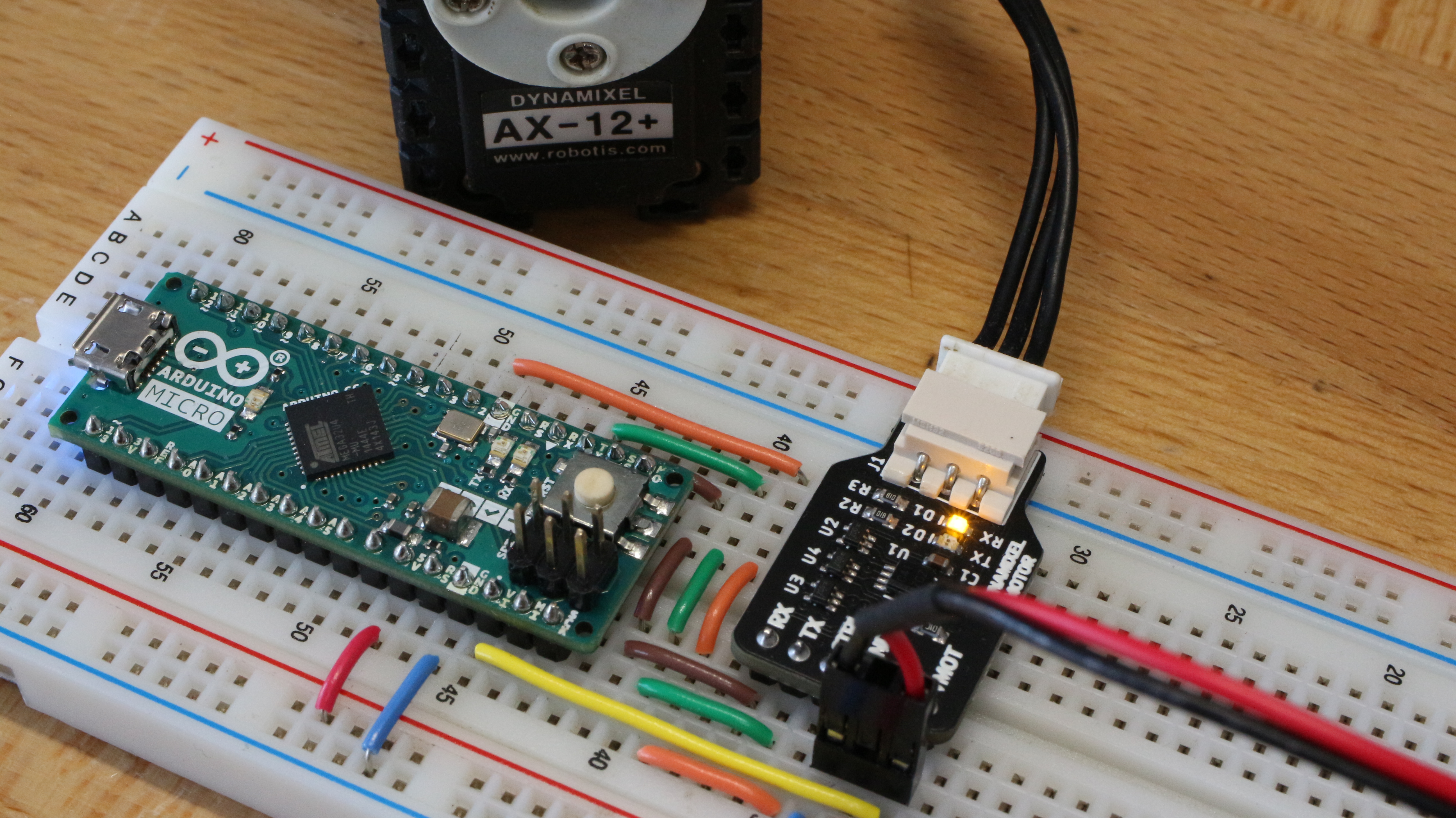
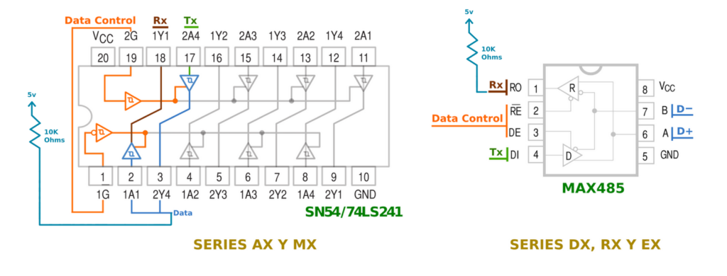
The connection to the MCU is as simple as providing power to the interface and connecting the 3 pins for the UART ( CTRL, TX, and RX ). I would use the following configuration for all the newest X-Series motors as well as for the old AX and MX Series motors with any 5V to 3.3V MCU like Arduino, PIC, STM, and ESP32.
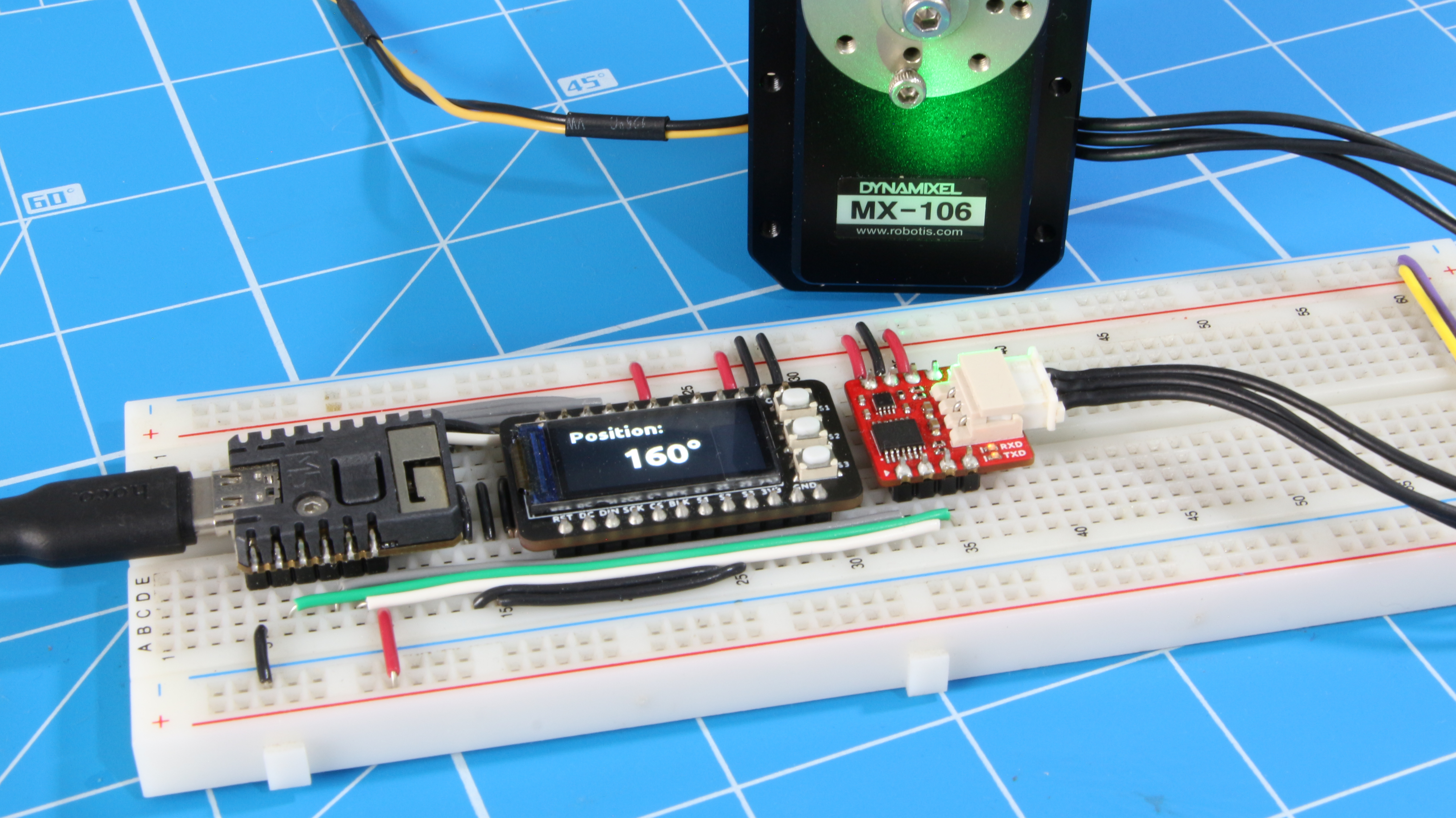
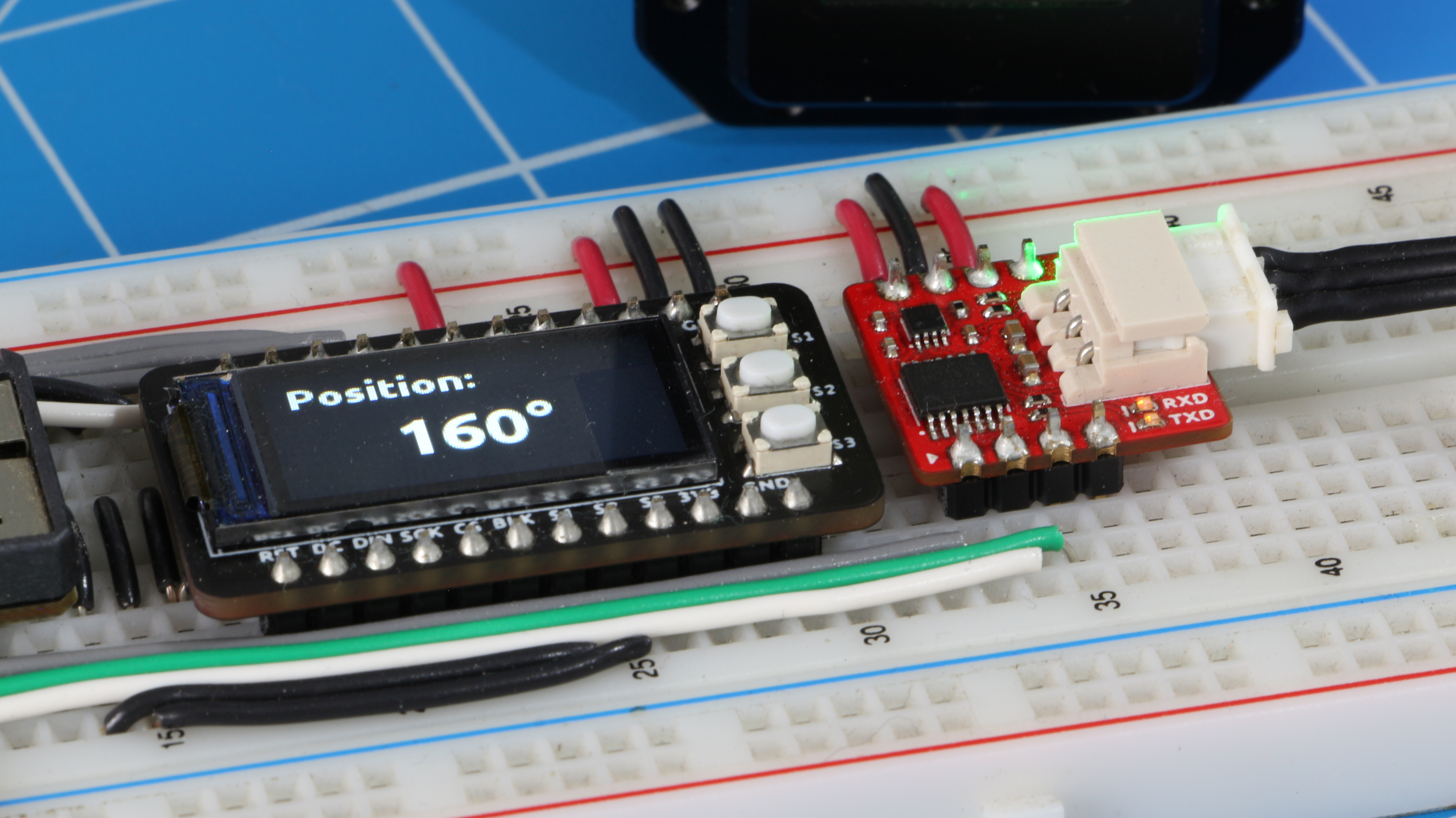
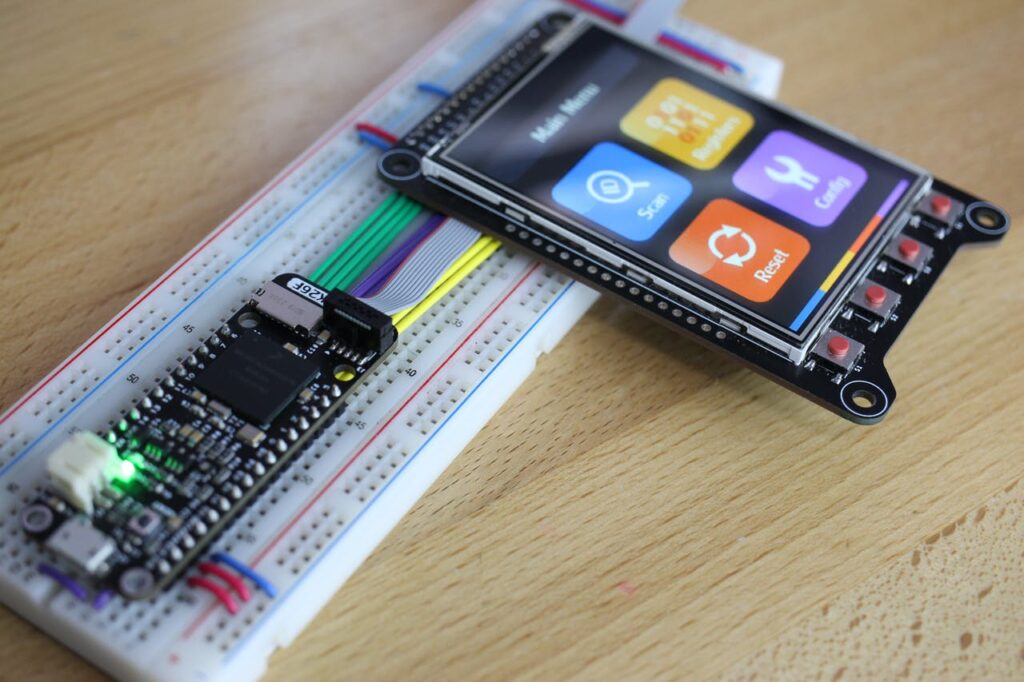
I have tested the interface with an M5Stack Stamp S3 MCU along with an ST7735 LCD showing the motor position and moving the motor with the 3 push-buttons.
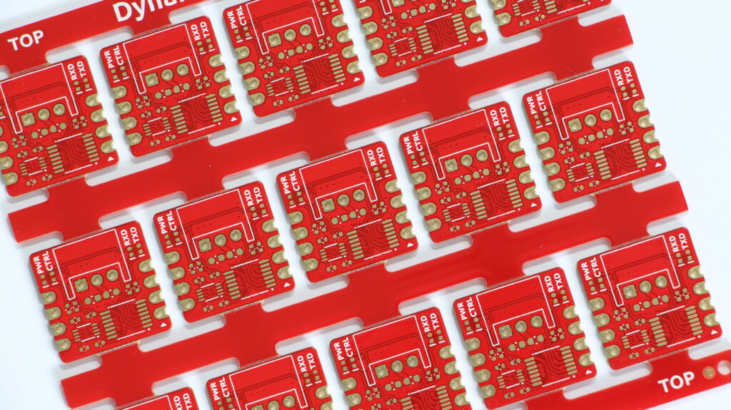
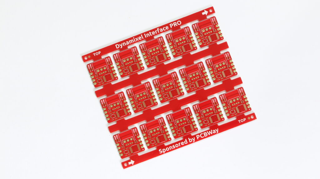
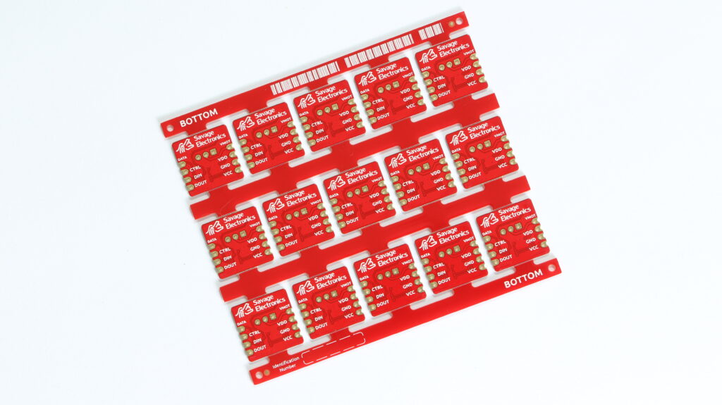
The castellated holes are one of the features that I most like about the PCBWay manufacturing skills, they always come just great even when choosing thinner PCB panels, and this design was not the exception, so I ordered some panels.
If you have intentions to fabricate more than one PCB of your design I really recommend panelizing your PCB in order to obtain the best deal and to have some spares in case the magic smoke decides to take some of those boards, I usually do my panels to fit almost the same PCB space as all my panels but you can also do your panel bigger or just let PCBWay to designed for you.
In this case, I decided to design my own Panel but I am sure that you can specify how would you like your panel to be made as some special silkscreen like identifications numbers, holes, fiducials, PCB batch number, PCB side, and feed direction for your PnP and so much more.
There has been sometimes that it has been hard to communicate with this type of smart motors, I don’t always remember the set ID or even the last configured baud rate for serial communication, or even the simple task of changing a single parameter requires to write a custom program to change that value to that specific motor, for that reason I decided to start building a handheld device that will make this kind of tasks easier and faster.
A simple UI in a TFT LCD will let configure these motors in a few steps, the project is going to integrate electronics used in other of my projects to make this development easier and faster, hoping to have feedback from the robotics community who have work with this kind of motors by letting me know the best path to follow.
In this first step I will have a first approach for the graphical interface, here are some ideas that I have tried, and the most recent one.
I will be using an ST7789V controller 2.8 inch TFT LCD for this project as I think it is a good size for the data it will work with. I will also be using the MK26F microcontroller that I have in a Feather format and a Dynamixel interface board for communication with the motors. So it needs to be all wired, connecting the SPI, ADCs, and GPIOs from the feather board to the TFT LCD Breakout board.
I have added some interesting things to the graphics for a more fluid and friendly interface as movement on the main menu icons, as shown in the next picture.
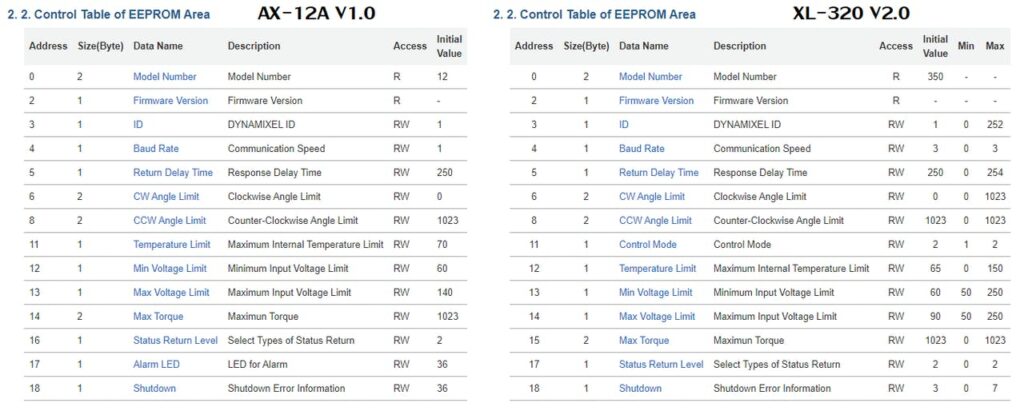
I have noticed that there are a lot of Dynamixel motors, the classic AX-12A use the protocol V1.0 but the newer one uses the V2.0 and also they change some registers address making this whole idea a bit difficult, I am still thinking how many motor models this device will support, as a first step I will make the firmware ready for the AX-12A and the XL-320 as I think are most popular one and also the cheapest.
The first step is to port the Dynamixel library for Arduino that I wrote many years ago to my microcontroller and then also update the library to be compatible with the V2.0 Dynamixel protocol.
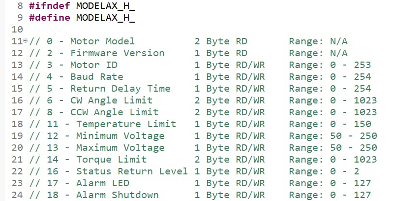
So there are some slight differences between registers address and all of this have to take in count when showing the info the configurator, so I have started to register this tables in a model file and maybe would be updated in a more compressible file in the future.
Motor scanning and selection menu
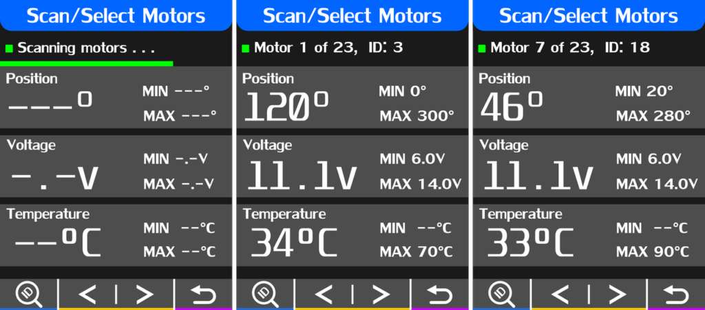
In order to test or modify the motor register, we need to scan and select the connected motors, for this task I have created a short function that Ping the bus and waits for each motor ID, and adds it to the motor list at a given baud rate and protocol.
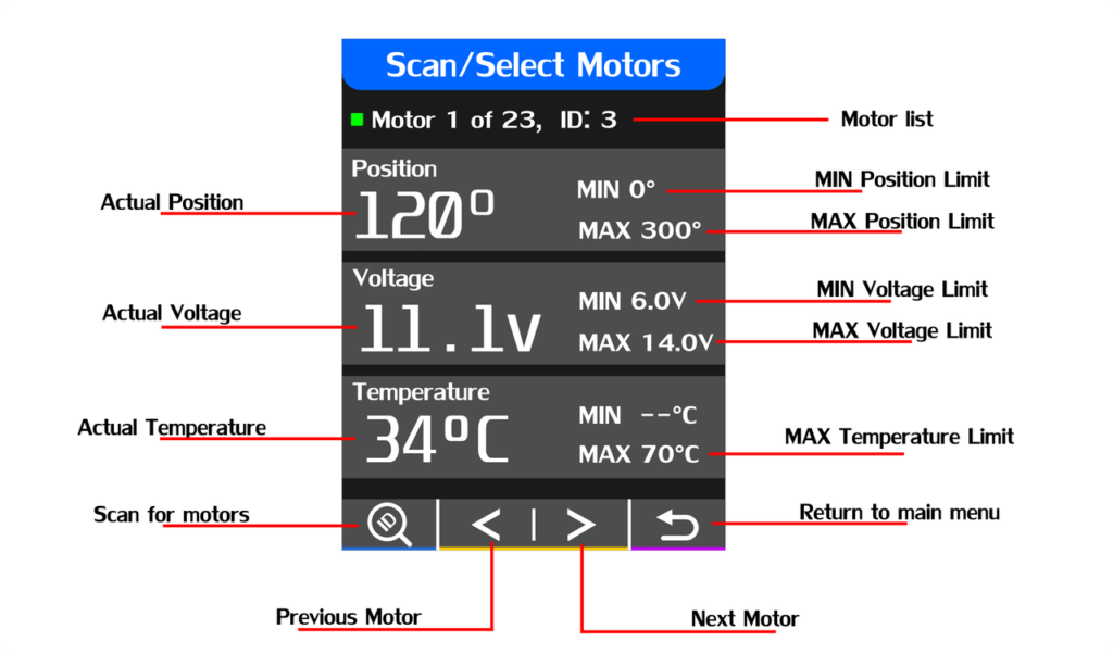
After the motor scanning, it’s useful to know certain values of the motor so I decided to read these and display them in the same window with the capability to scroll the motor list and at the same time select the motor of interest.
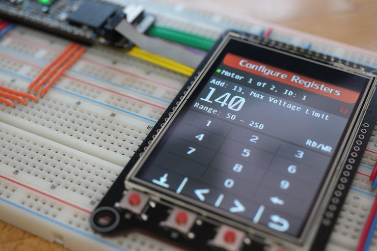
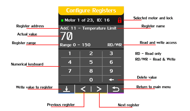
Configure Registers Window
In this window will be able to read and write directly to register of the selected motor in the previous windows, it will be accessible to both the EEPROM and RAM registers in order to properly test the written values, limits, or alarms.The new values will be written on a numerical touchscreen keyboard.
This window also shows if the EEPROM data is write-protected, in order to write the torque of the motor should be disabled, this can be done by writing a 0 to the Torque Enable register in address 24.
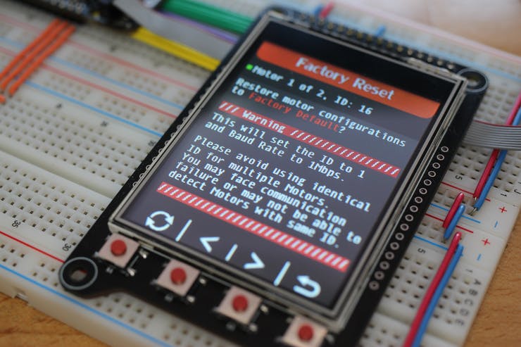
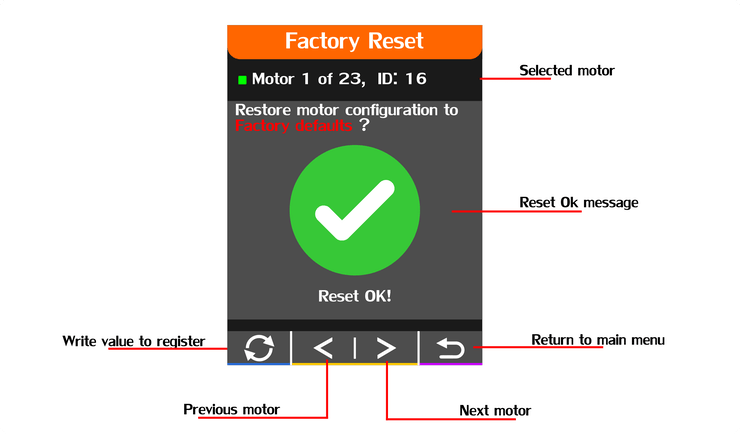
Factory Reset Window
The factory reset window is a simple but very efficient way to restore motor parameters to factory defaults with a press of a button.
This option will perform a reset function on the Dynamixel instructions set, so all it been handled by the motor itself, the motor list is also accessible from this window but it has to be in consideration that motors should not have the same ID as it can cause errors in the communication.
When a reset has finished successfully this window will also inform and will let you continue with the reset operations that you may need for other motors.
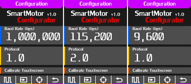
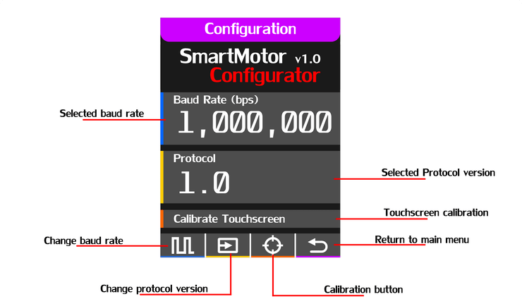
Configuration Window
The configuration windows allow to change the Baud rate speed, the Dynamixel protocol and perform a touchscreen calibration if needed.
As you havealready noticed the touchscreen calibration options are accessible with the tact switches in case that the touchscreen valueshave changed over time, the only action that needs the touchscreen is the keyboard on the register configuration window.
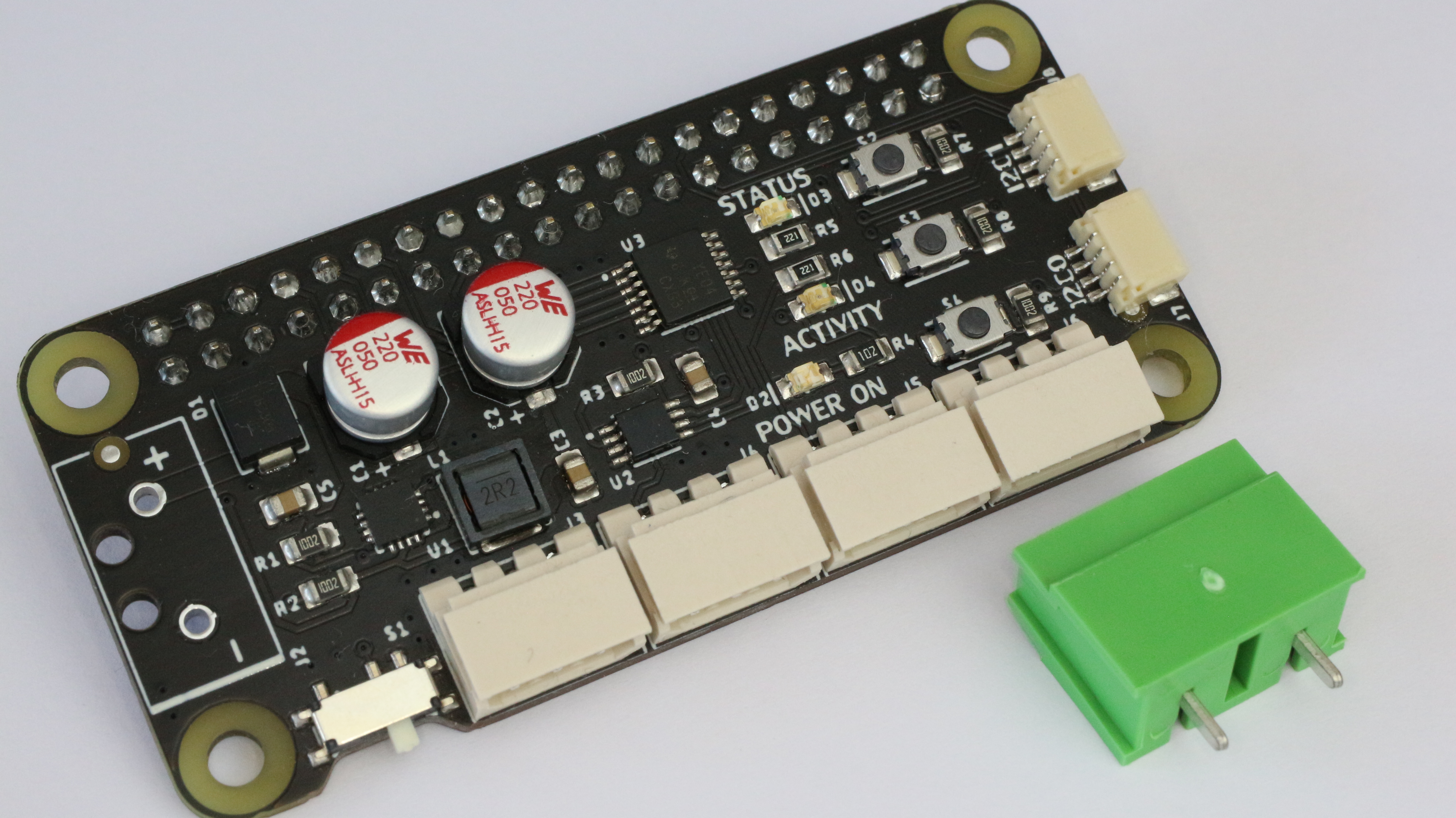
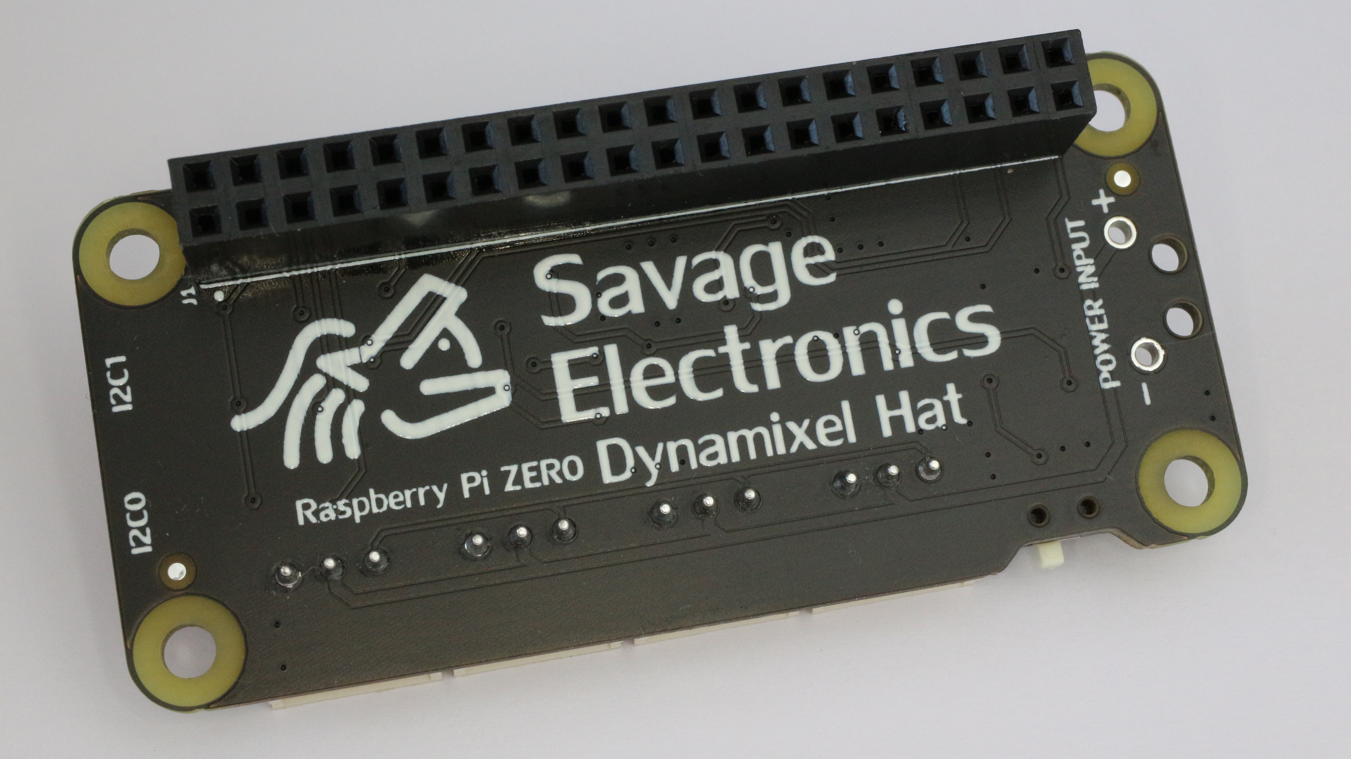
The Dynamixel Hat is a board capable of communicating the raspberry Pi ( Serial ) with the Dynamixel servos by using the 74LS241 Tri-state Buffer connected to 3-pin Molex connectors.
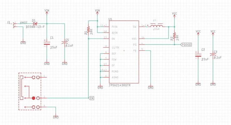
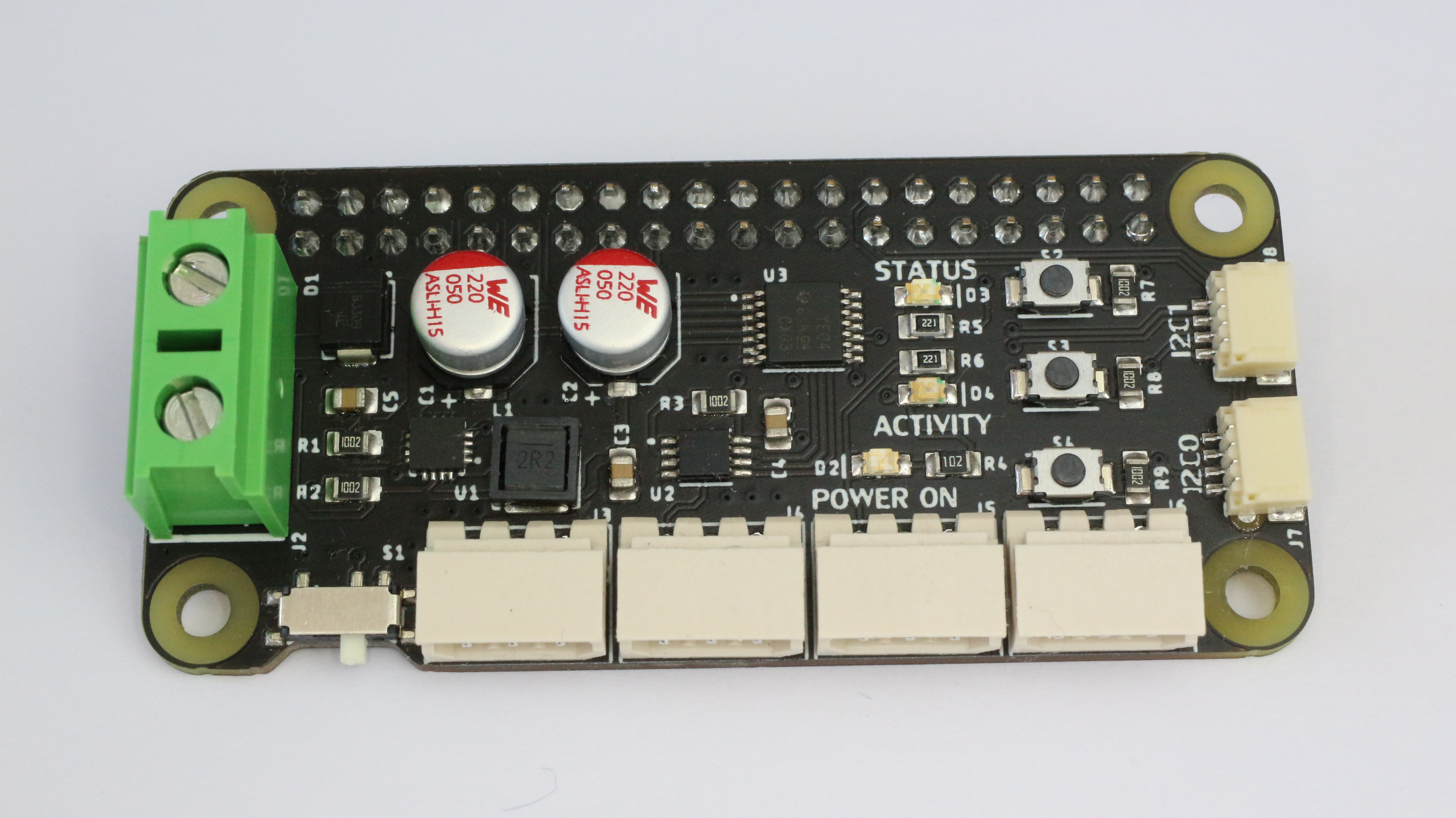
The board contains a TI TPS62143 regulator that steps down the voltage to power up the Raspberry Pi Zero that can be power on or off with the onboard slide switch. The TPS62143 is a synchronous step-down DC-DC converter optimized for applications with high power density.
This board accepts 2S and 3S Lipo batteries, the DC-DC converter accepts up to 17 Volts but the motors recommended voltage is 11.1V ( 3S Lipo ) as the MAX Input voltage is around 16 Volts.
The boards incorporate two I2C ports for sensors for your robotic project. These are JST 1 mm pitch and 4-pin connectors compatible with many boards on the QWIIC family.
There are also 3 LEDs and 3 Buttons for notification and interaction with the electronics, the buttons are programable through the Raspberry GPIOs and 1 LED also GPIO Configurable, the other 2 LEDs are the Activity and PowerOn notification.
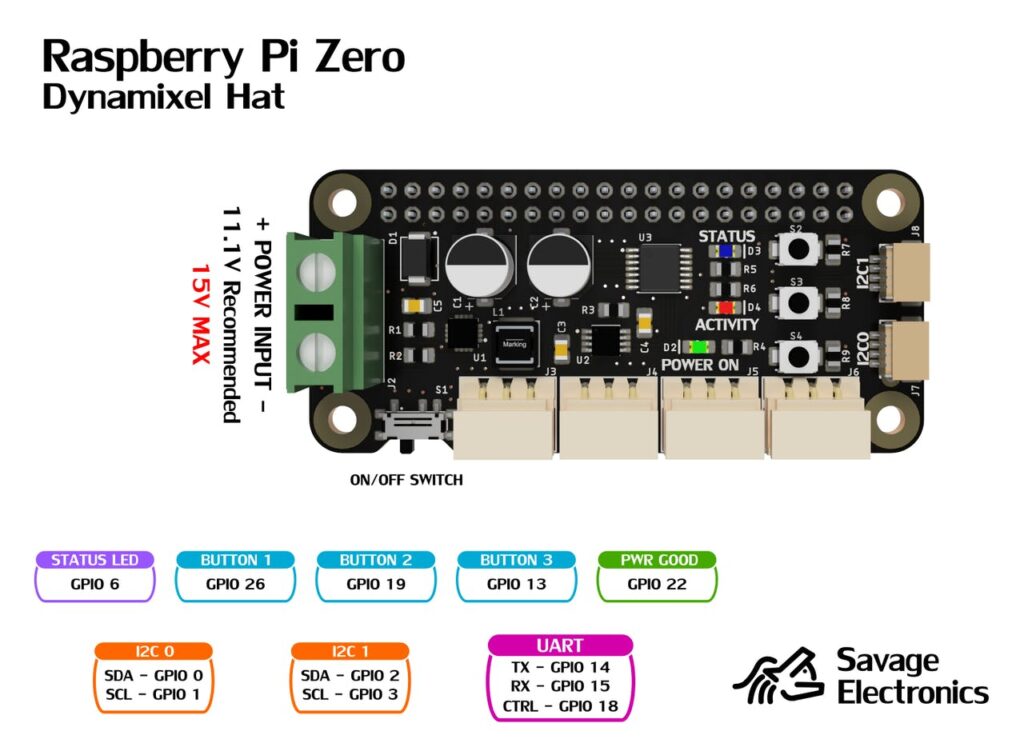
Pinout
Test code:
import RPi.GPIO as GPIO
import serial
import time

GPIO.setwarnings(False)
GPIO.setmode(GPIO.BCM)
GPIO.setup(18,GPIO.OUT)     # Control Data Direction Pin
GPIO.setup(6,GPIO.OUT)      # Blue LED Pin

GPIO.setup(26,GPIO.IN)      # S2 Push Button Pin
GPIO.setup(19,GPIO.IN)      # S3 Push Button Pin
GPIO.setup(13,GPIO.IN)      # S4 Push Button Pin


Dynamixel=serial.Serial("/dev/ttyS0",baudrate=1000000,timeout=0.1, bytesize=8)   # UART in ttyS0 @ 1Mbps


while True:

    if GPIO.input(26):
        GPIO.output(6,GPIO.LOW)
    else:
        GPIO.output(6,GPIO.HIGH)
        GPIO.output(18,GPIO.HIGH)
        Dynamixel.write(bytearray.fromhex("FF FF 01 05 03 1E CD 00 0B"))  # Move Servo with ID = 1 to position 205
        GPIO.output(18,GPIO.LOW)
        startDynamixel = Dynamixel.read()
        startDynamixel = Dynamixel.read()
        idDynamixel = Dynamixel.read()
        lenghtDynamixel = Dynamixel.read()
        errorDynamixel = Dynamixel.read()
        chkDynamixel = Dynamixel.read()
        print("Servo ID = " , int.from_bytes(idDynamixel,byteorder='big') , " Errors = ", int.from_bytes(errorDynamixel,byteorder='big'))
        time.sleep(1)

    if GPIO.input(19):
        GPIO.output(6,GPIO.LOW)
    else:
        GPIO.output(6,GPIO.HIGH)
        GPIO.output(18,GPIO.HIGH)
        Dynamixel.write(bytearray.fromhex("FF FF 01 04 02 2A 01 CD"))   # Read Voltage of Servo with ID = 1
        GPIO.output(18,GPIO.LOW)
        startDynamixel = Dynamixel.read()
        startDynamixel = Dynamixel.read()
        idDynamixel = Dynamixel.read()
        lenghtDynamixel = Dynamixel.read()
        errorDynamixel = Dynamixel.read()
        voltDynamixel = Dynamixel.read()
        chkDynamixel = Dynamixel.read()
        print("Servo Voltage = " , int.from_bytes(voltDynamixel,byteorder='big'))
        GPIO.output(18,GPIO.HIGH)
        Dynamixel.write(bytearray.fromhex("FF FF 01 04 02 2B 01 CC"))   # Read Temperature of Servo with ID = 1
        GPIO.output(18,GPIO.LOW)
        startDynamixel = Dynamixel.read()
        startDynamixel = Dynamixel.read()
        idDynamixel = Dynamixel.read()
        lenghtDynamixel = Dynamixel.read()
        errorDynamixel = Dynamixel.read()
        tempDynamixel = Dynamixel.read()
        chkDynamixel = Dynamixel.read()
        print("Servo Temperature = " , int.from_bytes(tempDynamixel,byteorder='big'))
        GPIO.output(18,GPIO.HIGH)
        Dynamixel.write(bytearray.fromhex("FF FF 01 04 02 24 02 D2"))   # Read Position of Servo with ID = 1
        GPIO.output(18,GPIO.LOW)
        startDynamixel = Dynamixel.read()
        startDynamixel = Dynamixel.read()
        idDynamixel = Dynamixel.read()
        lenghtDynamixel = Dynamixel.read()
        errorDynamixel = Dynamixel.read()
        posDynamixel = Dynamixel.read(2)
        chkDynamixel = Dynamixel.read()
        print("Servo Position = " , int.from_bytes(posDynamixel,byteorder='little'))
        time.sleep(1)

    if GPIO.input(13):
        GPIO.output(6,GPIO.LOW)
    else:
        GPIO.output(6,GPIO.HIGH)
        GPIO.output(18,GPIO.HIGH)
        Dynamixel.write(bytearray.fromhex("FF FF 01 05 03 1E 32 03 A3"))    # Move Servo with ID = 1 to position 816
        GPIO.output(18,GPIO.LOW)
        startDynamixel = Dynamixel.read()
        startDynamixel = Dynamixel.read()
        idDynamixel = Dynamixel.read()
        lenghtDynamixel = Dynamixel.read()
        errorDynamixel = Dynamixel.read()
        chkDynamixel = Dynamixel.read()
        print("Servo ID = " , int.from_bytes(idDynamixel,byteorder='big') , " Errors = ", int.from_bytes(errorDynamixel,byteorder='big'))
        time.sleep(1)
Enable UART at 1Mbps in your Raspberry Pi Zero
Make sure to add the following to your Raspberry config file at /boot/config.txt:
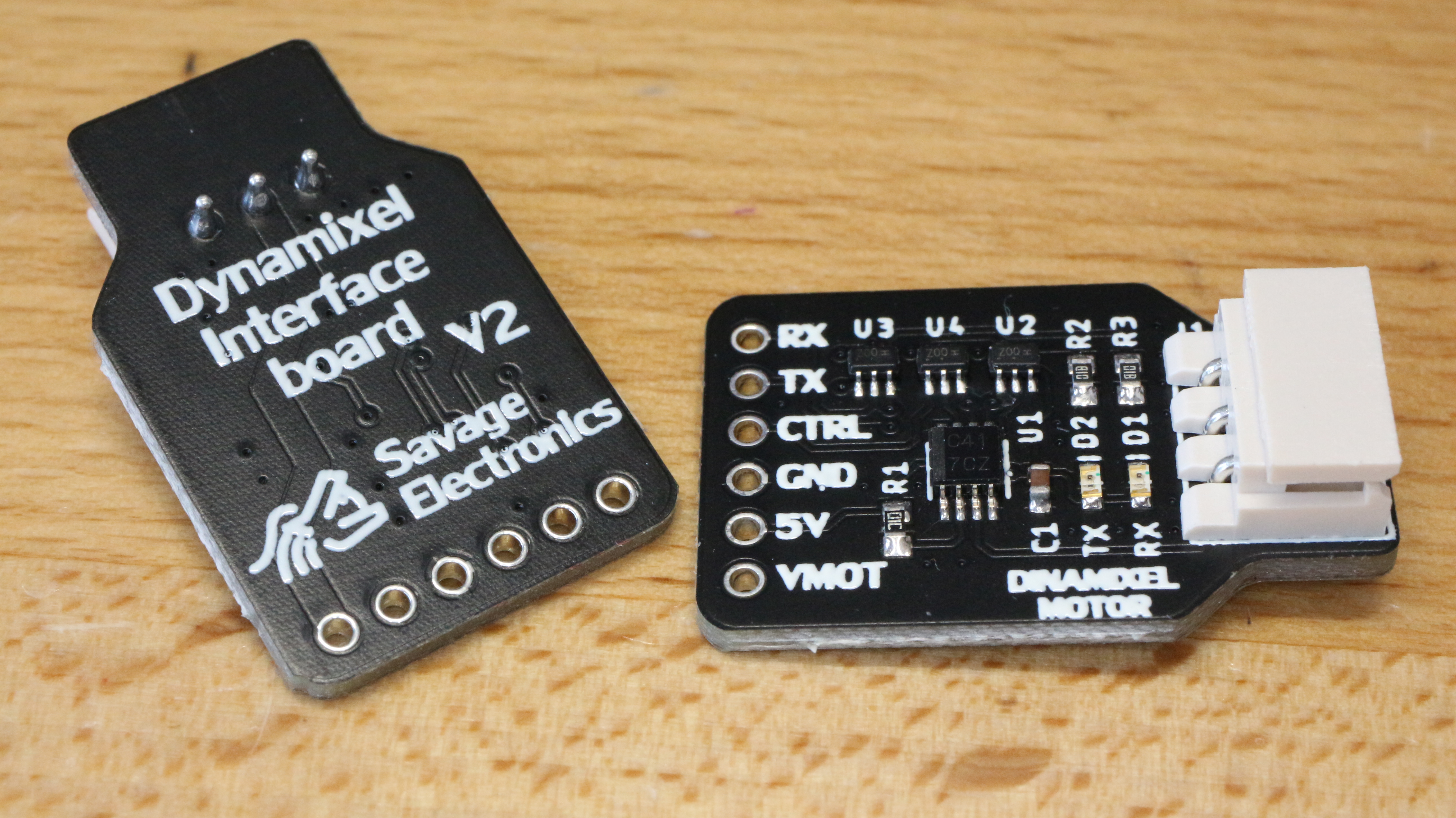
I have decided to redesign the Dynamixel interface and put it again in stock on my Tindie store, this redesign include some status LEDs that visually let you know if the motor is communicating to the motors and vice-versa, I have also decided to change the connector orientation which makes the board a little bit compact and more compatible with small dimensions projects.
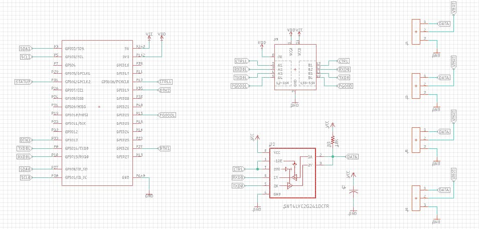
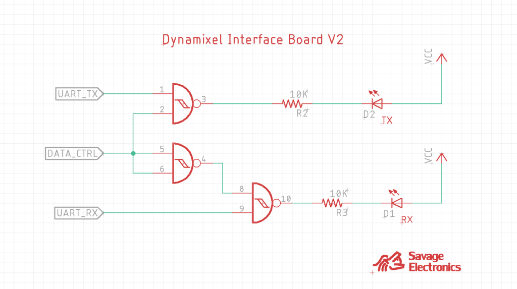
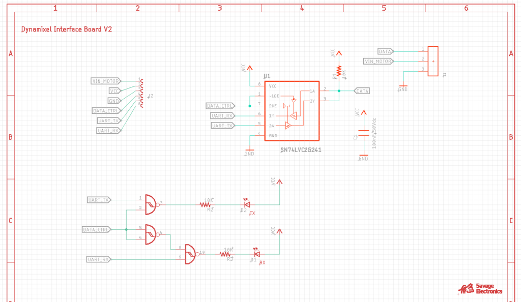
The circuit for the LED indicators uses some NAND gates that let the user know when data is going to the servo and from the servo to the microcontroller without the need for a logic analyzer.
This update is a very simple update and it does not affect the functionality of the interface, it is just a visual benefit for the user.
Here is the schematic in case you have the components and wish to make your own interface.
Test code:
#include <DynamixelSerial.h>

#define SERVO_ID  1
int Temperature,Voltage,Position;

void setup(){
Dynamixel.setSerial(&Serial1); // &Serial - Arduino UNO/NANO/328P, &Serial1, &Serial2, &Serial3
Dynamixel.begin(1000000,2);    // Inicialize the servo at 1 Mbps and Pin Control 2
Serial.begin(9600);            // Begin Serial Comunication
}

void loop(){
  Temperature = Dynamixel.readTemperature(SERVO_ID); // Request and Print the Temperature
  Voltage = Dynamixel.readVoltage(SERVO_ID);         // Request and Print the Voltage
  Position = Dynamixel.readPosition(SERVO_ID);       // Request and Print the Position

  Dynamixel.move(1,random(200,800));

  Serial.print("Temperature: ");                  // Print the variables in the Serial Monitor
  Serial.print(Temperature); Serial.print(" celcius, ");
  Serial.print("Voltage: ");
  Serial.print(float(Voltage)/10);Serial.print(" volts, ");
  Serial.print("Position: ");
  Serial.println(Position);

  delay(1000);
}
After a long time here is an update in the Library for Dynamixel Sero Motors as the AX-12A.
These servos are pretty awesome, they seem the perfect solution for robotics as they can return several parameters as internal temperature, the voltage of operation, position, speed, torque, and all of this is accomplished as they have an internal microcontroller, the Atmega8 from Atmel which communicates over Half-Duplex UART TTL. This library helps you communicate with the Dynamixel Servos protocol V1.0 in any of the Serial channels of your Arduino.
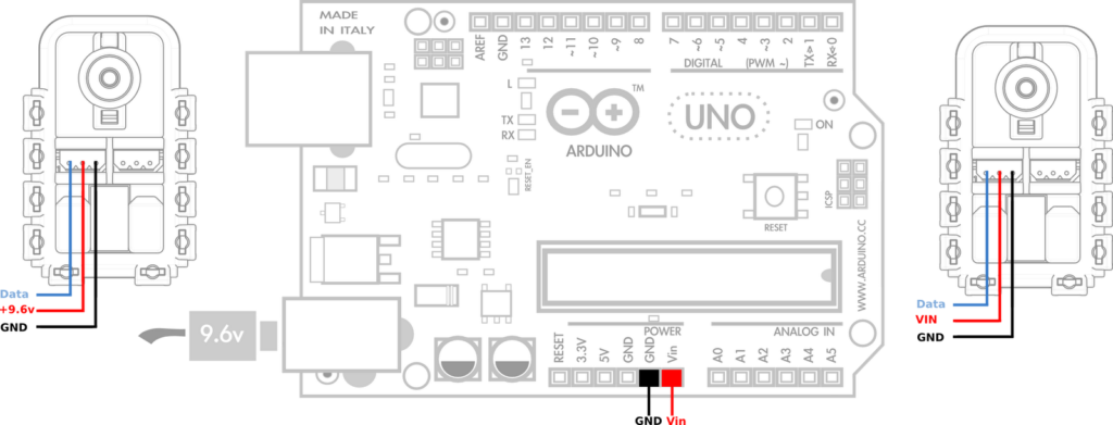
The voltage of operation of these motors is recommended to be 11.1 volts, but it should work ok from 6V to 14V as the datasheet describes in the electrical ratings. Don’t forget to join the grounds of your motor’s power supply and the one from the microcontroller in other to level the signal voltage between them.
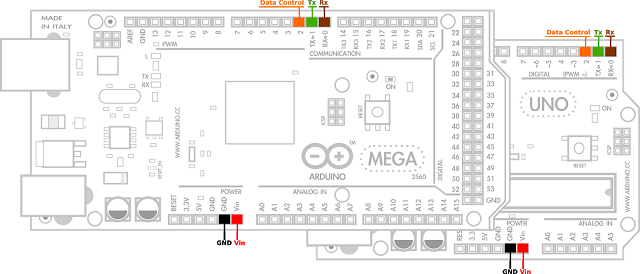
Power supply connectionArduino UART pins connection
In order for this library to work and to ensure proper usage it is necessary to use a tri-state buffer IC, this can be achieved with a 74HC04 NOT gate and a 74HC126 tri-state buffer ICs ad Robotis suggests. I personally prefer the 74LS241 tri-state buffer with inverted enable pin input as is easy to connect and offers the same configuration in a single IC.
Don’t forget the VCC and GND IC power supply connections, VCC should be 5V