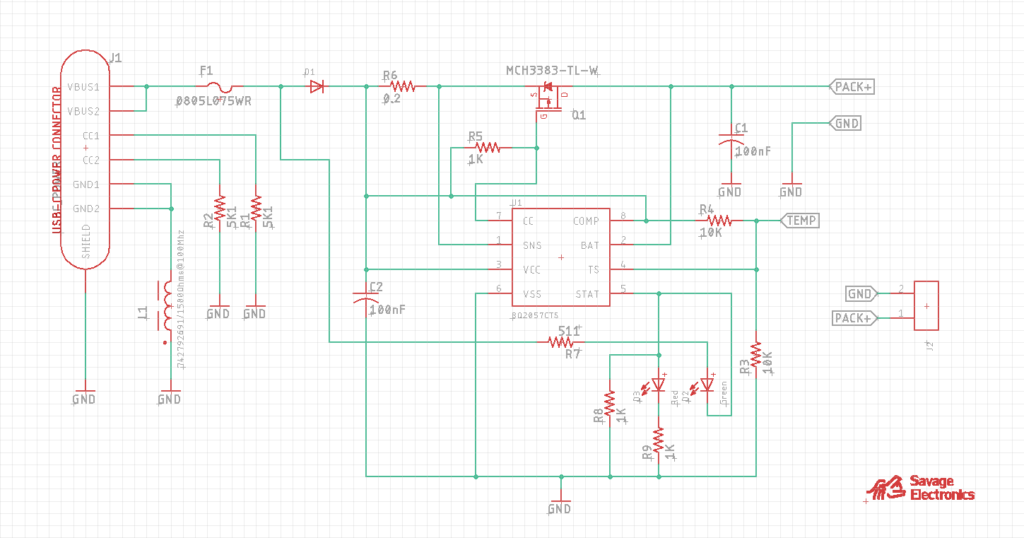
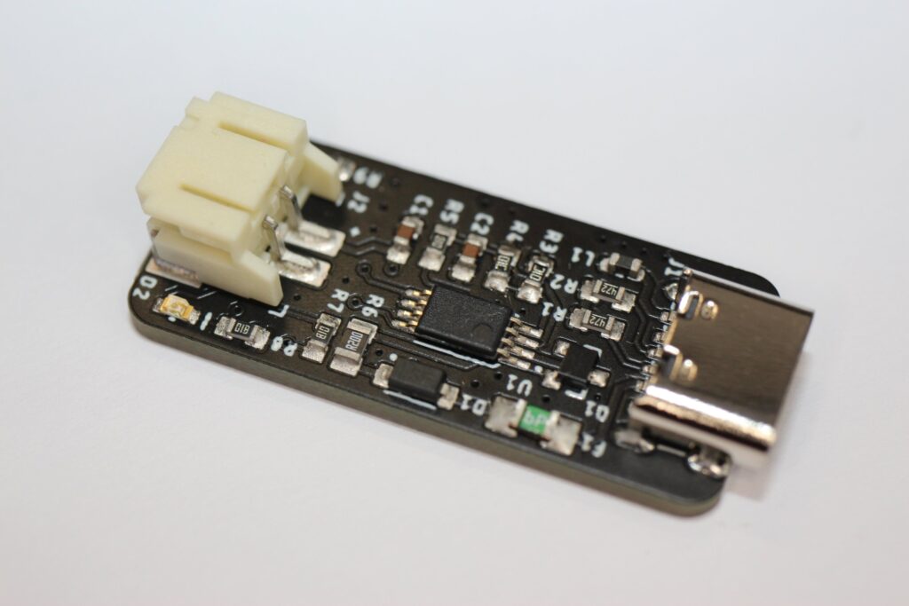
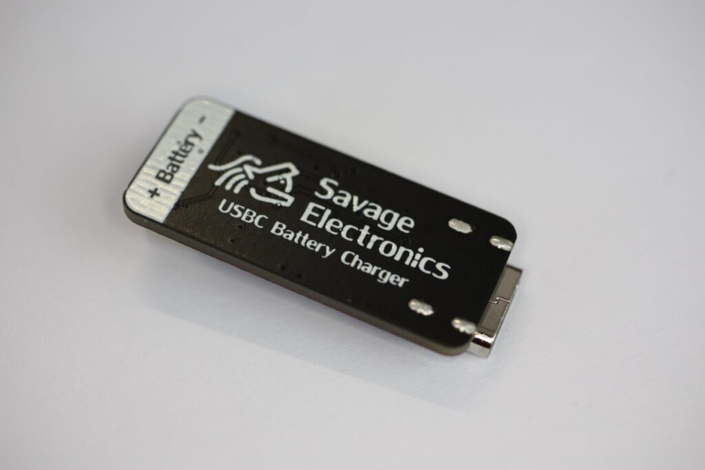
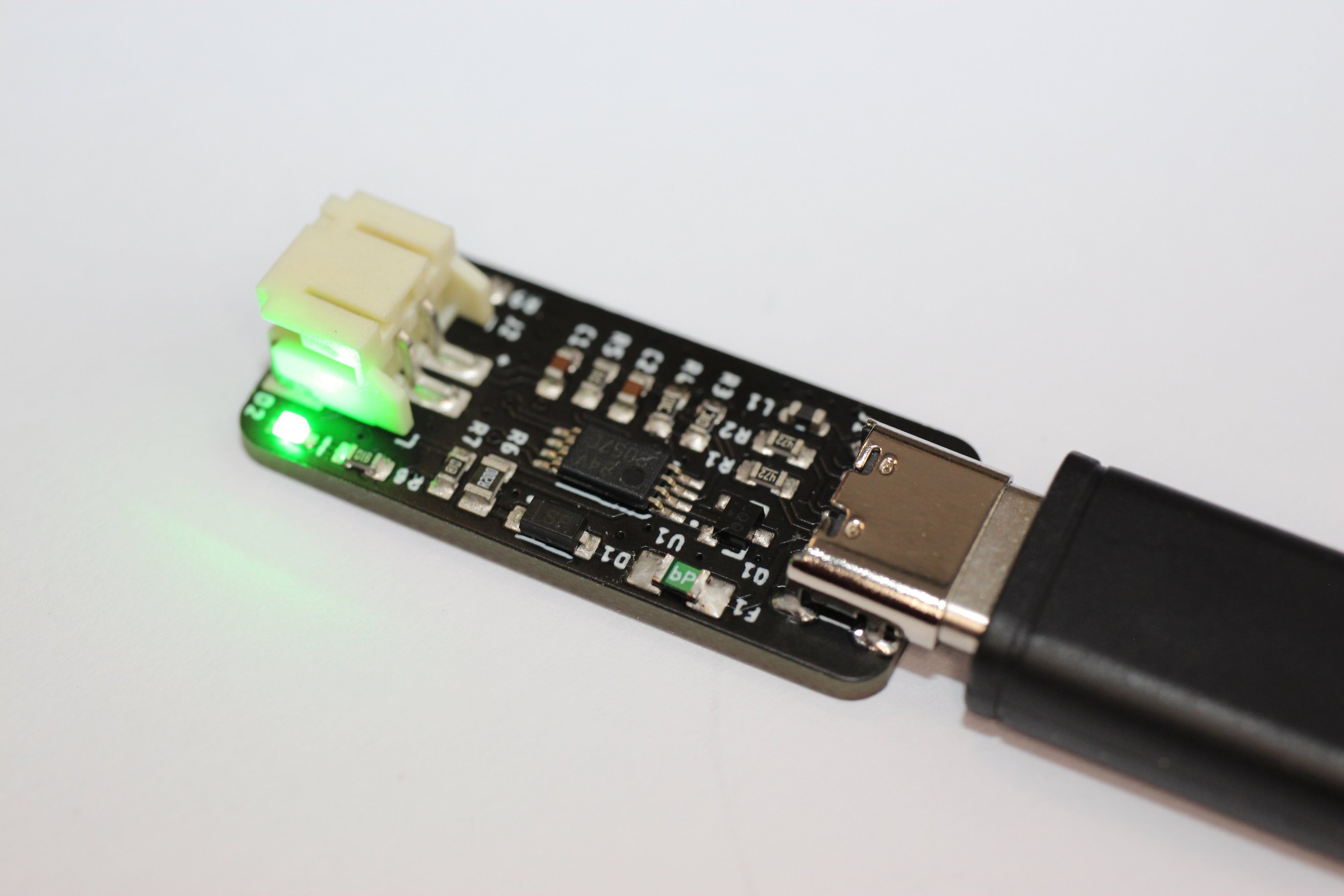
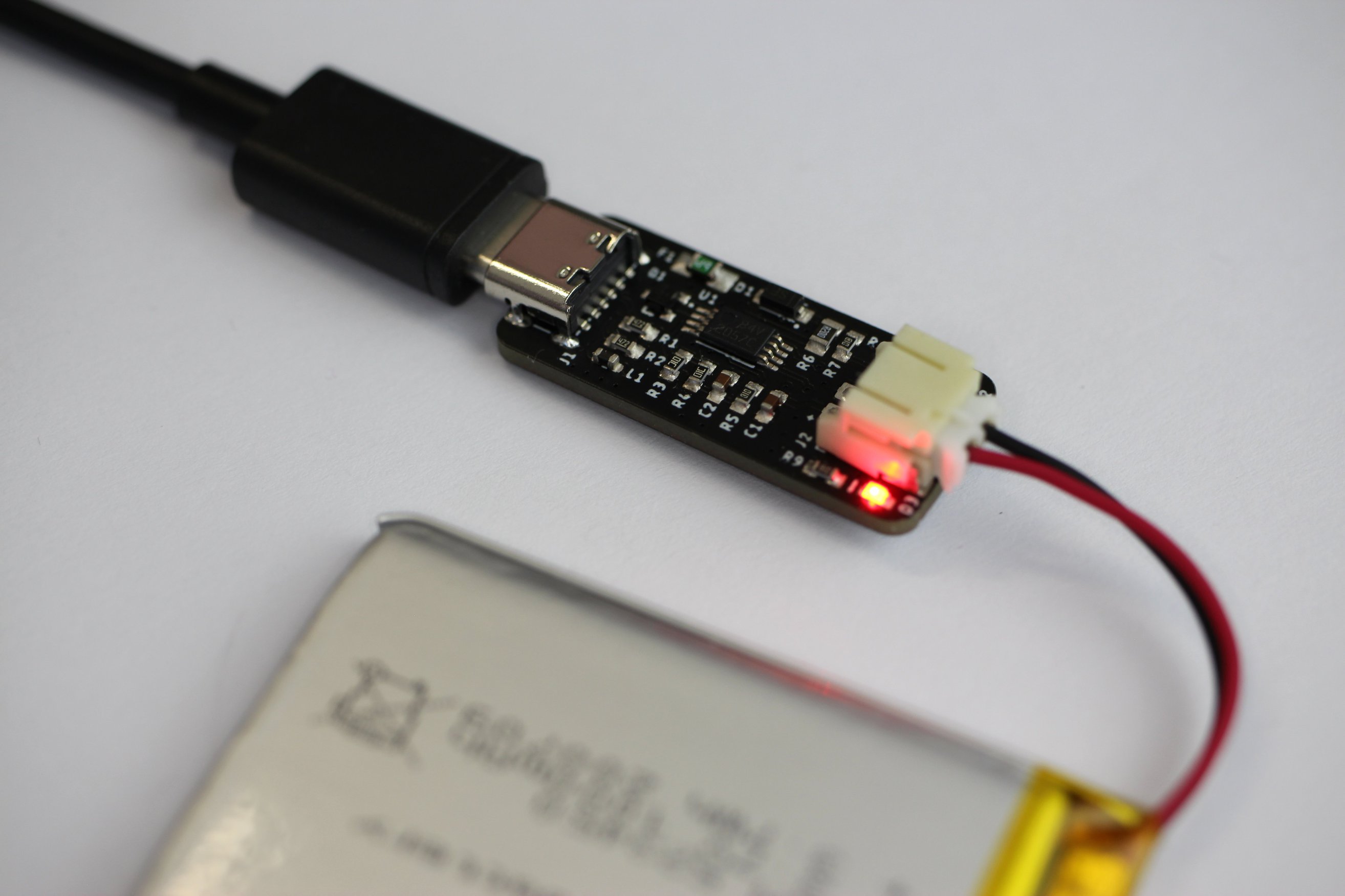
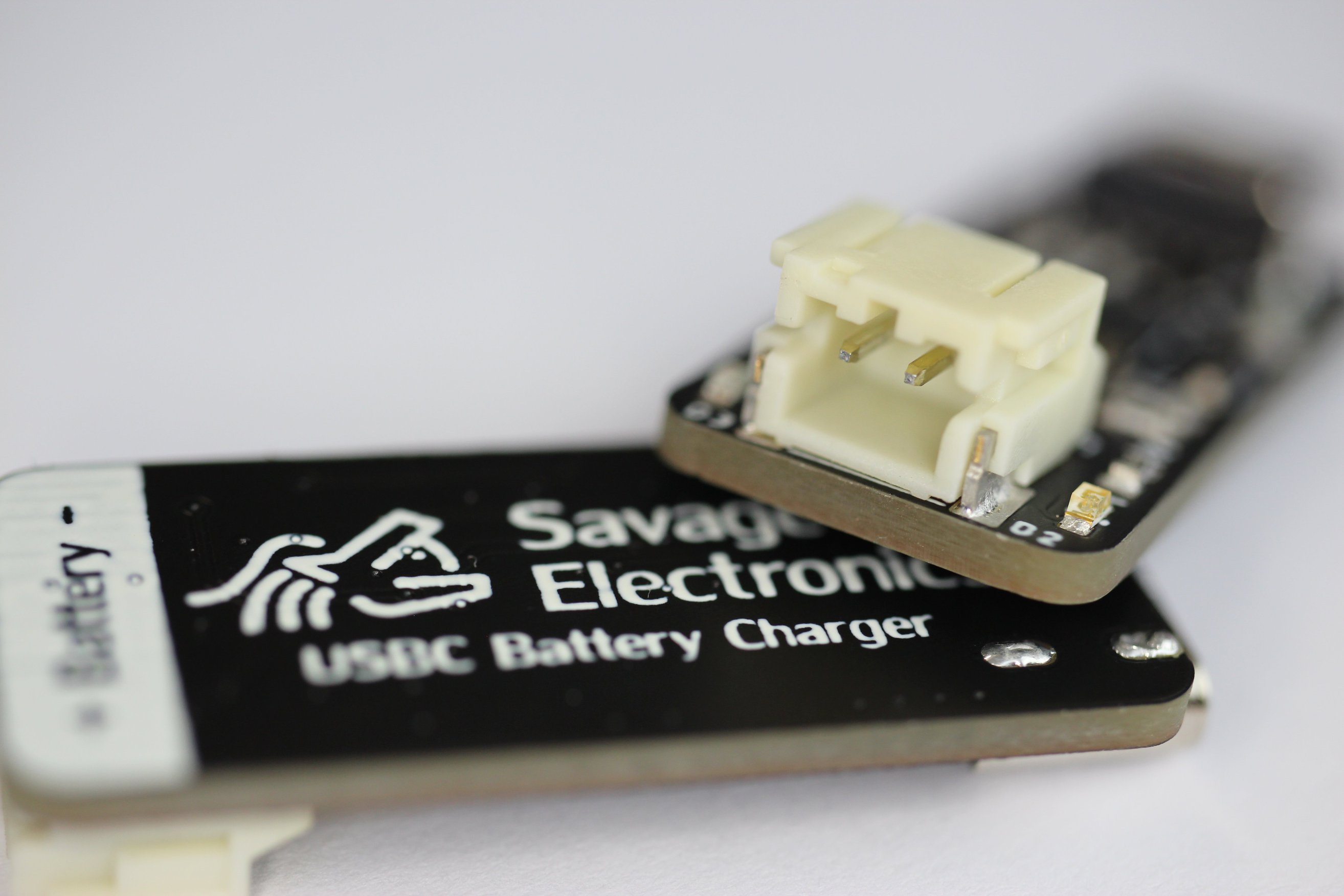
It is a useful USBC Lipo Battery charger with the Texas instruments BQ2057 Low Dropout linear 1-cell Li-ion charge controller with indication LEDs, with a charge current of 500mA.
It is nowadays easier to have in hand a USB-C Connector on hand like our Phone charger and I really prefer this kind of connector to the old standard MicroUSB.
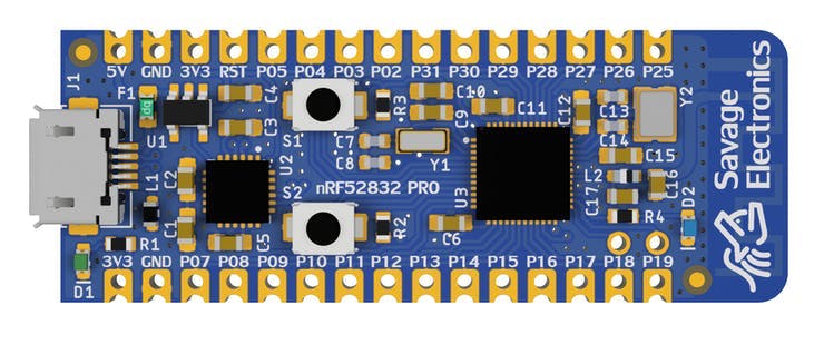
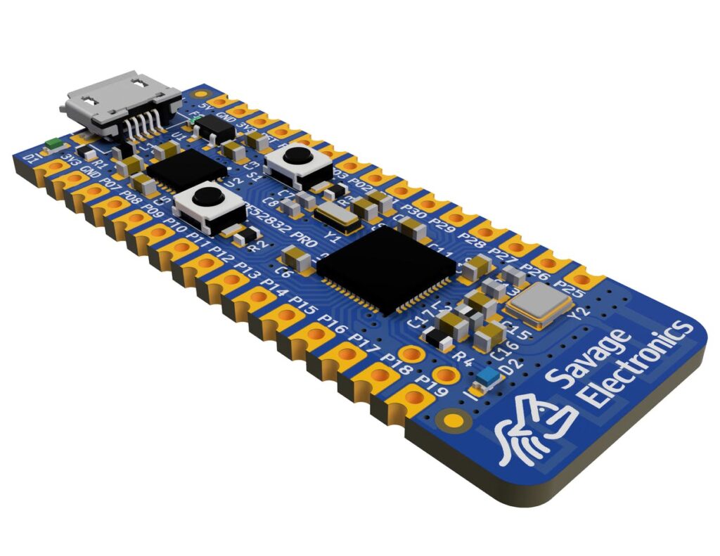
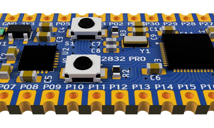
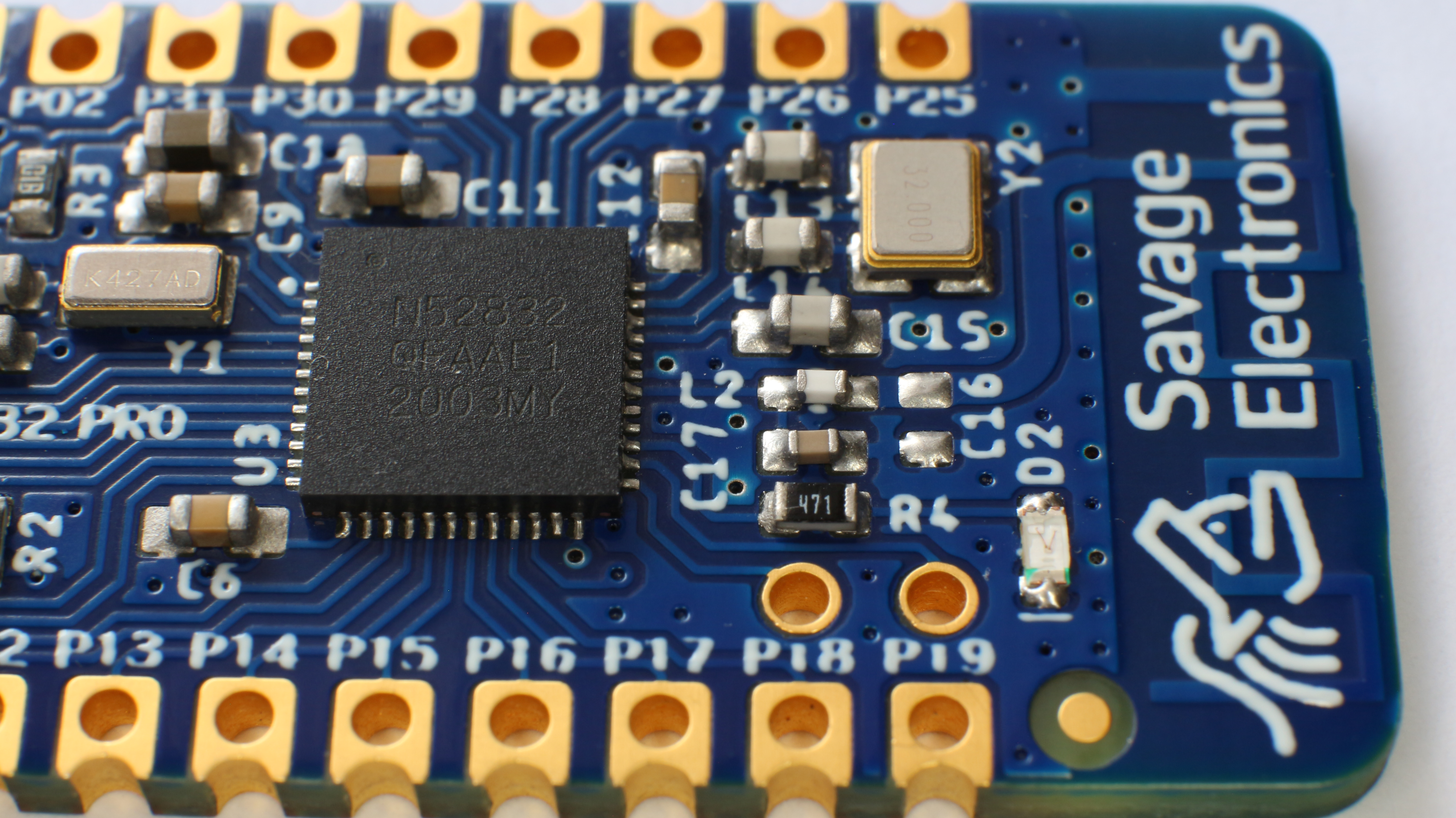
This is a new project using the nRF52832 BLE MCU as a very versatile development platform that will allow me to do many projects that requires a connection over Bluetooth and also can perform actions to control basic systems, as data acquisition, data display, motor control, graphical interfaces and much more.
This board dimension is 48x18mm with 30 castellated holes on the side, a micro USB connector for power, and programming through a USB to serial converter CP2104, two tactile switches for user interface and firmware programming, 1 user LED.
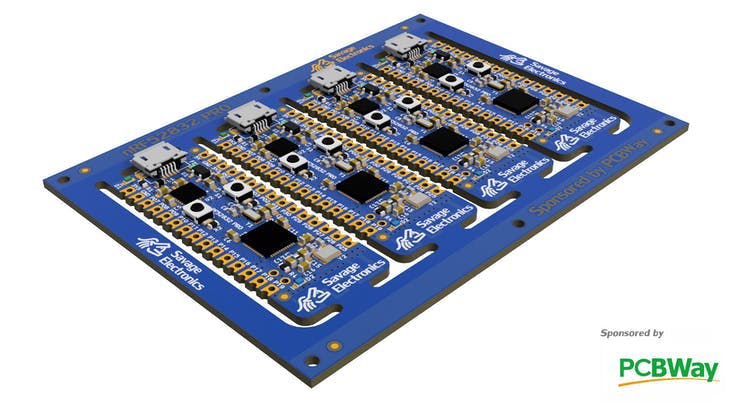
I have made a small panel for easy fabrication, This panel dimensions are 92x66mm including the tooling rails at the sides. In this panel I want to test several things that a usually do not order in a regular PCB, such as tooling rails with tooling holes, external fiducial, Logo with EING finish at the top tooling rail, solder mask and cooper restrictions for text and logos, and castellated holes in a routing job, v-score at the edges of the board as well on the tooling rails.
I quoted this panel in many PCB Manufacturing houses and order some boards for the best price in the market that includes all the characteristics described above with PCBWay. (Even cheaper than the well-know 2 USD – 5PCS PCB Manufacturing House).
These board are now getting manufactured, the customer service has been awesome so far, as I ask to place the UL Marking on the Top Silkscreen layer in the bottom layer of this panel and received a preview of confirmation of this requirement, and received awesome feedback regarding the Vscore and Solder mask capabilities.
Making this board possible required some knowledge in PCB Manufacturing that I will below describe the research and application.
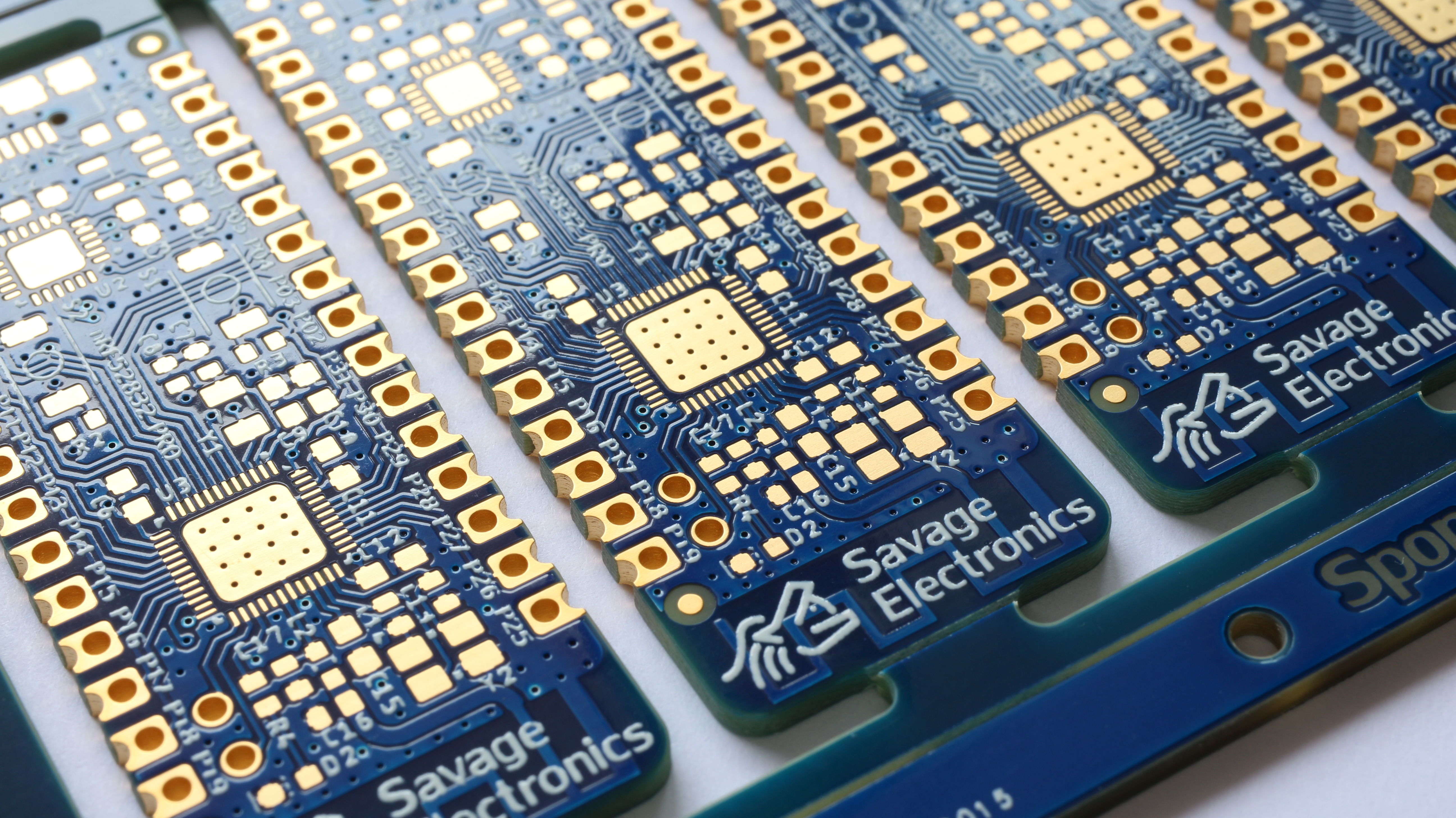
Castellated Holes: Also know as castellations are plated through-holes or vias at the edge of a board cut in the middle by a router making them pads that can be soldered to another PCB and make subassemblies.
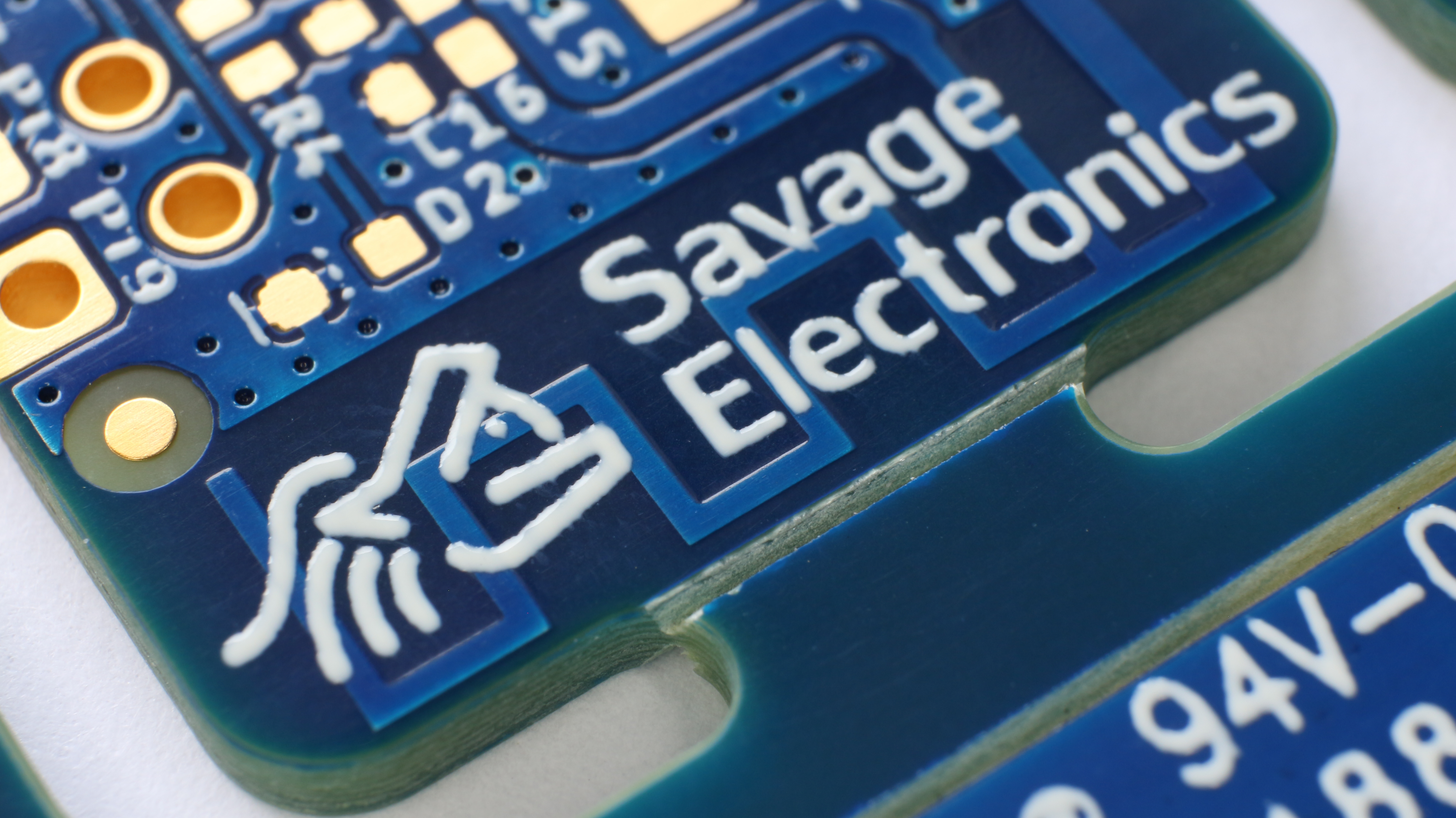
The PCBs have finally arrived, here are some photos.
If you are thinking about ordering some PCBs and start your own prototypes I recommend you to try PCBWay.
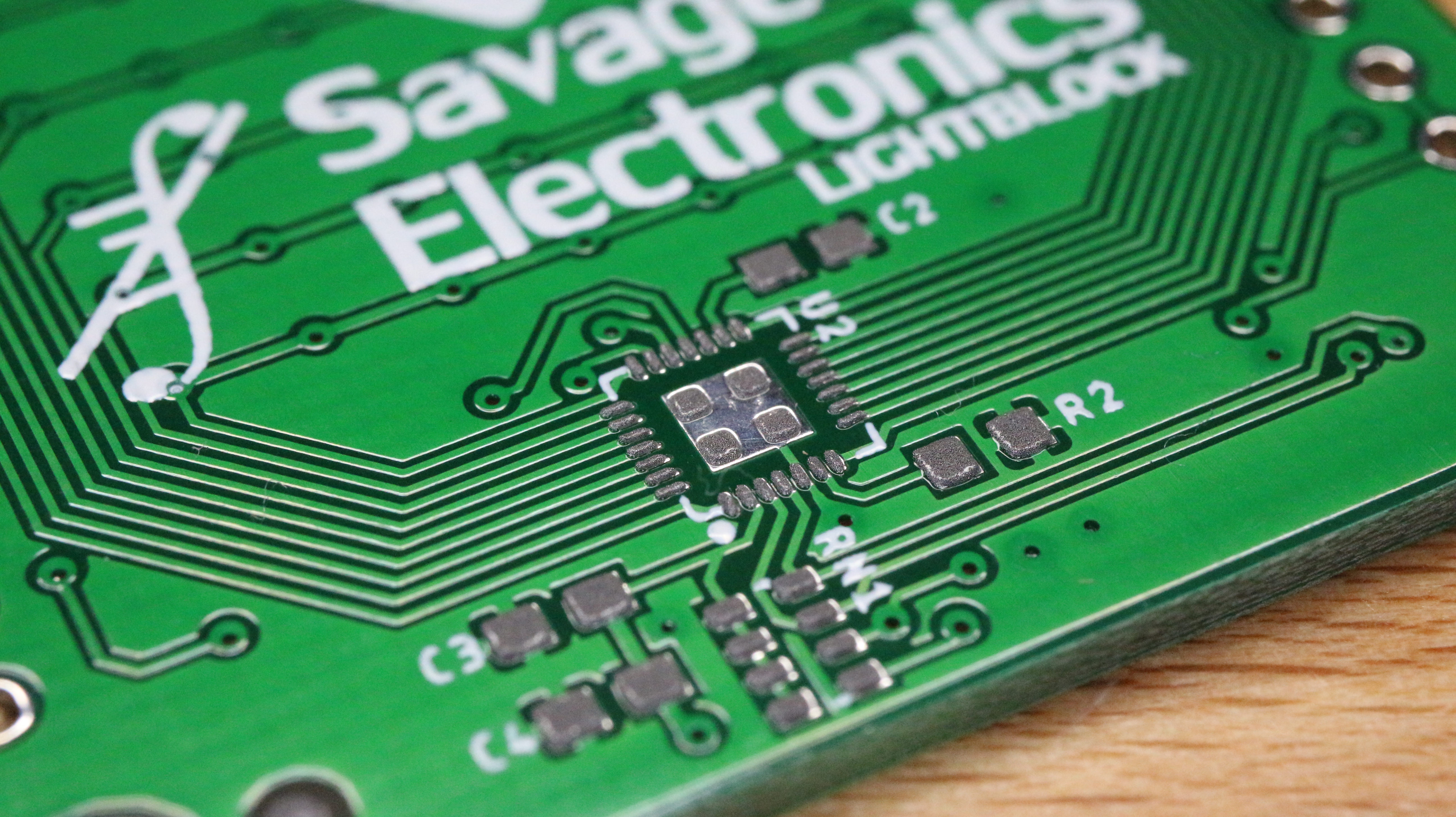
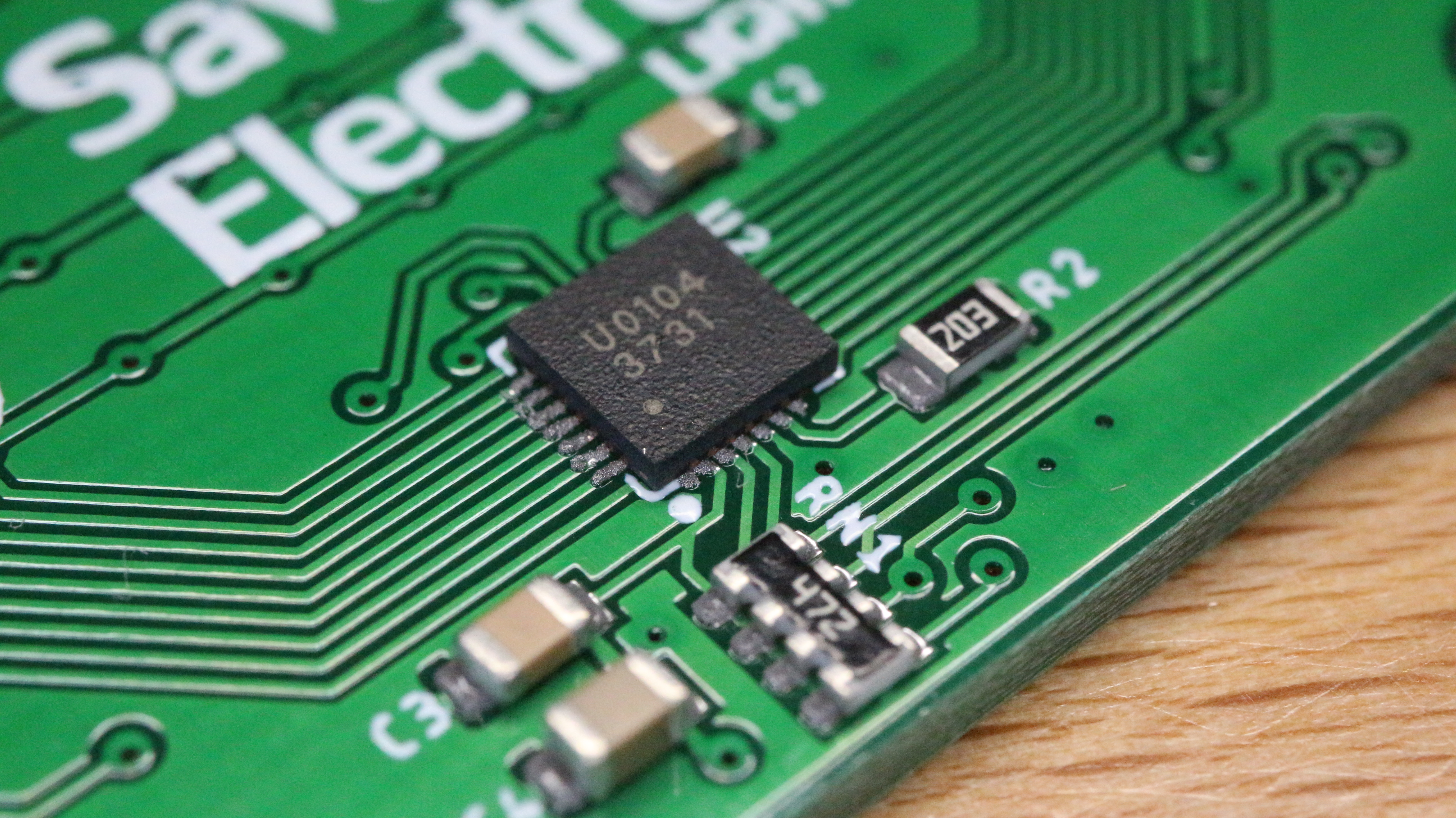
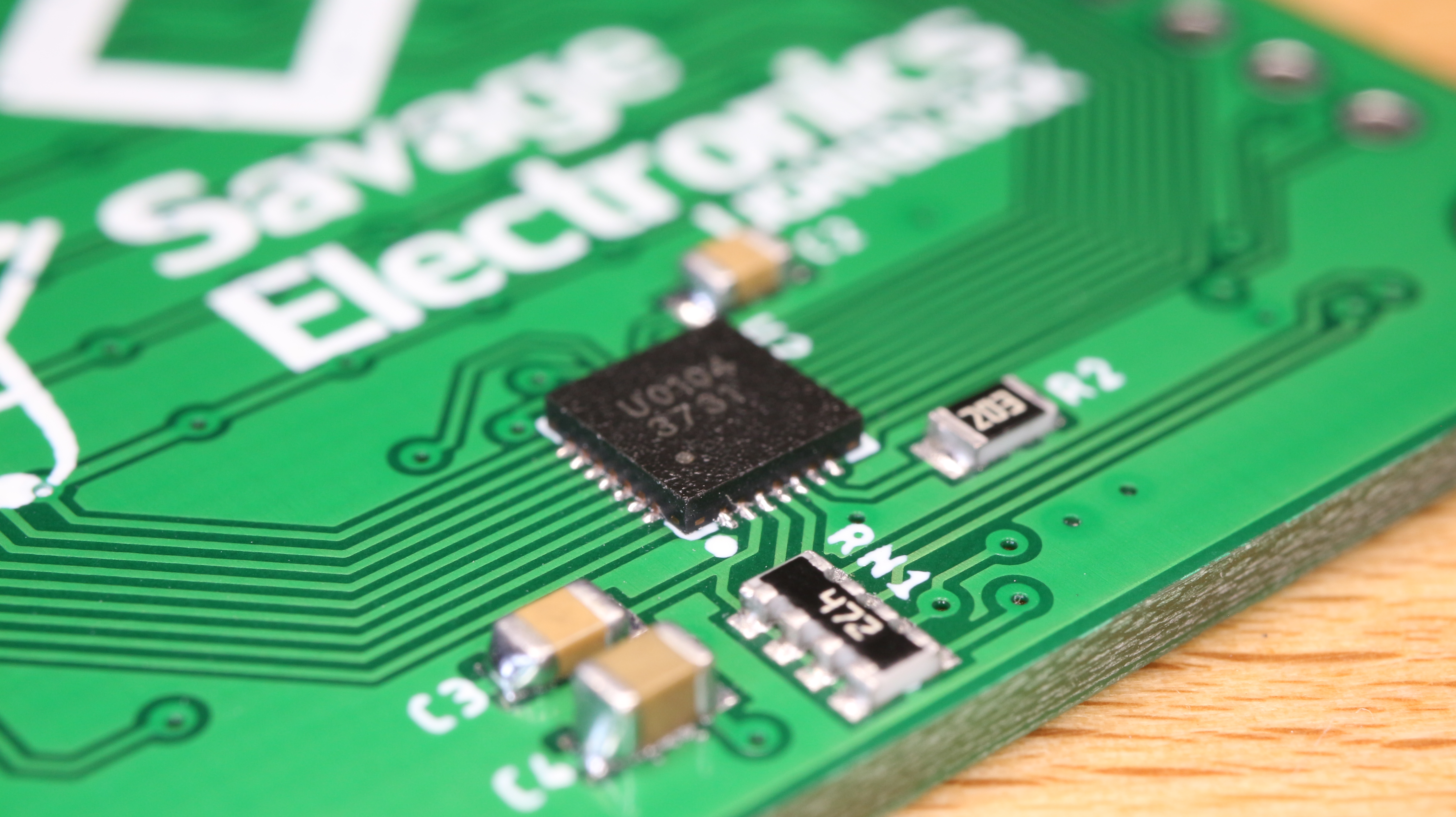
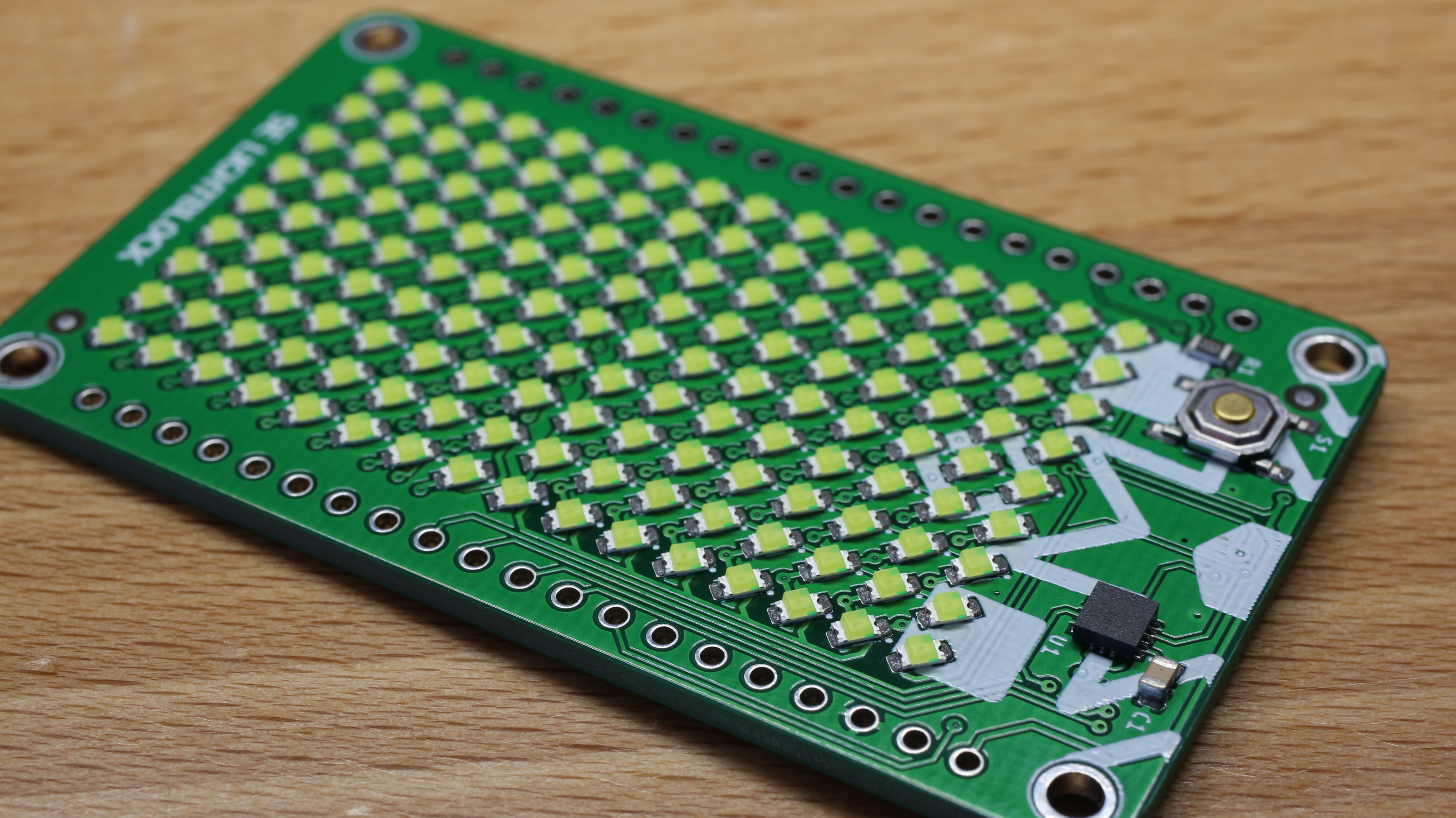
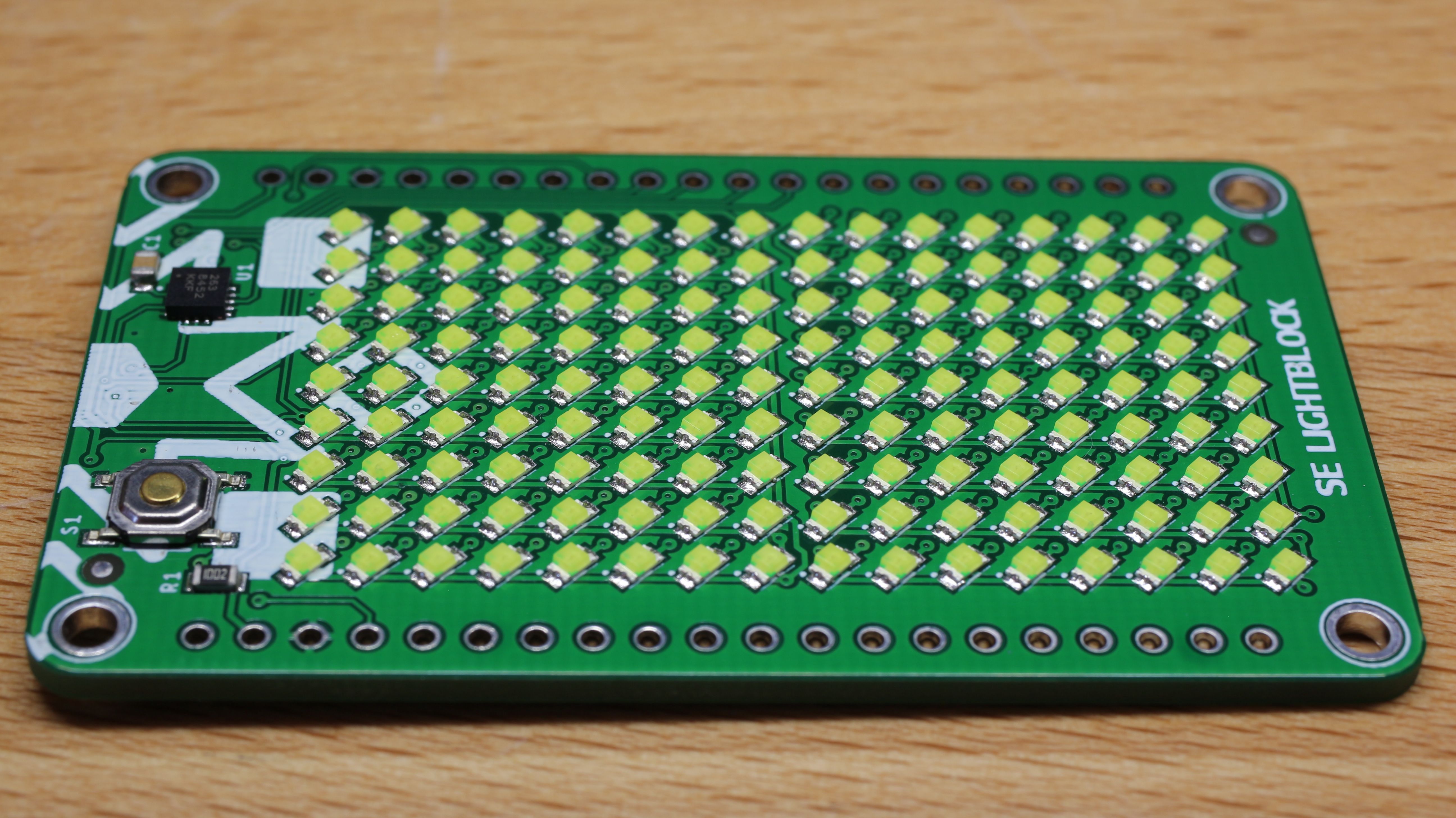
The IS31FL3731 from ISSI is an LED driver that uses cross-plexing in order to control up to 144 LED with a PWM of 8 bits, it also has on-chip memory to store 8 complete frames for animations and an input pin for audio interaction.
I design this board to test this chip and also added an MMA5284 Accelerometer from NXP, this board has components on both sides so I decided to solder the components with solder paste a the T962 reflow oven.
A very important step when you solder with a reflow oven it is to correctly apply the solder paste to the PCB, for better results it highly recommended to use a steel stencil and apply the solder paste in a single movement for proper solder quantity to the board.
After applying the solder paste just pick and place the components and reflow them in the oven and proceed with the other side of PCB the same way as previously.
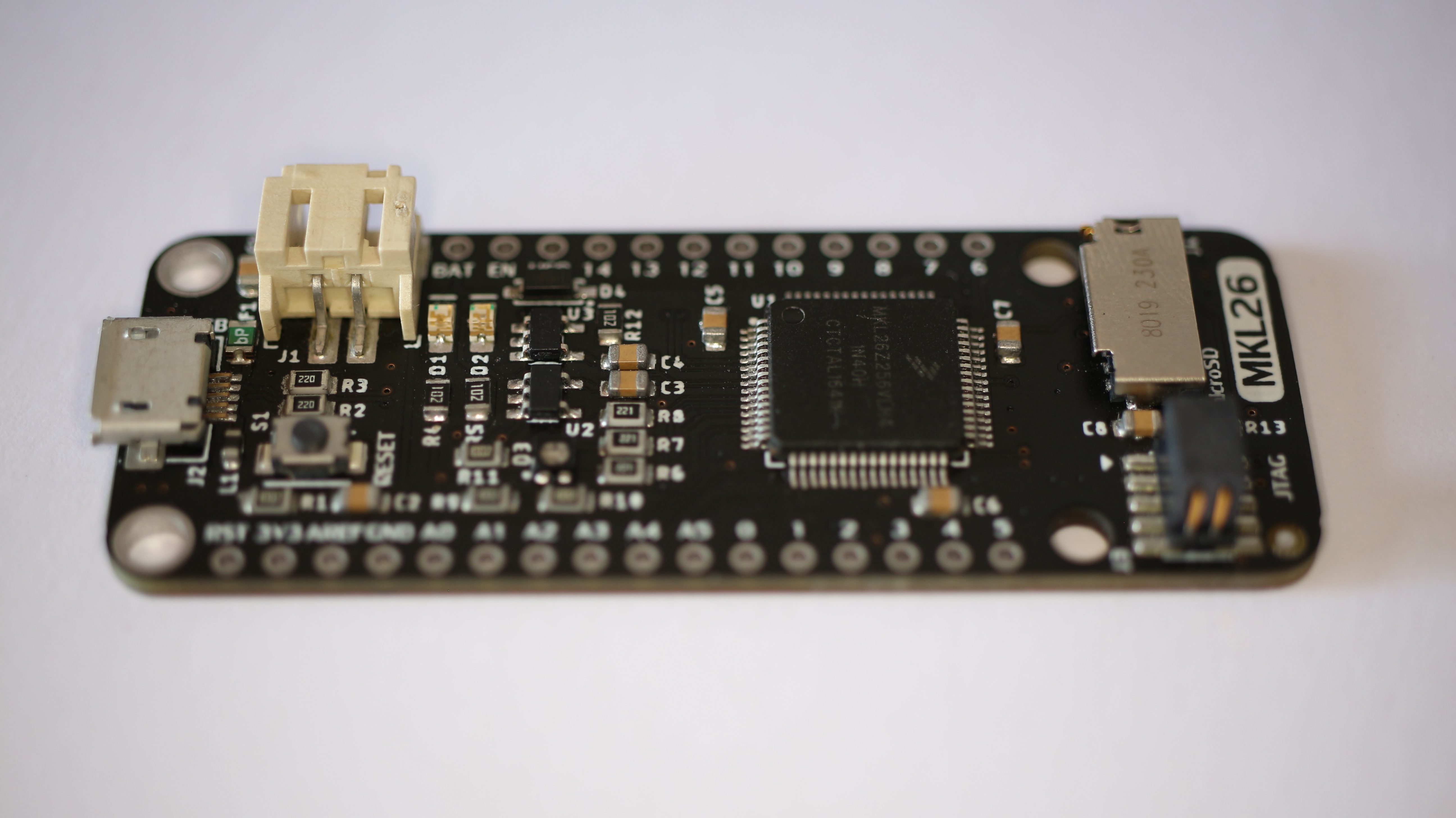
Most of the Adafruit Feather use microcontrollers from Atmel, Esspresif and Nordic and it’s hard to find them with other brand microcontrollers, There are some feathers with the newest NXP Crossover MCUs, and that is why I have decided to add some MID-Range and Low power consumption ones.
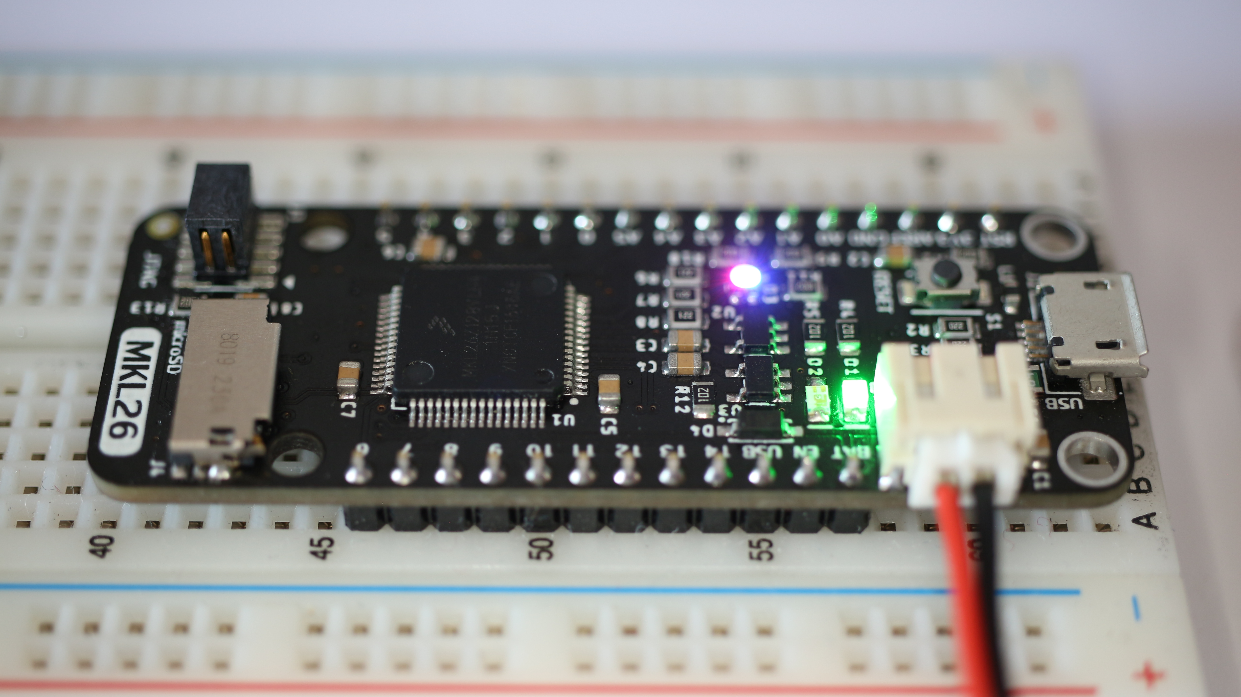
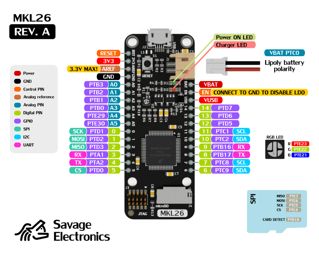
The MKL26 Feather is a board that packs the NXP/Freescale MKL26 which has an ARM Cortex M0+ core at 48Mhz with 256kb of Flash and 32Kb of RAM. The board includes a microSD socket and RGB LED.
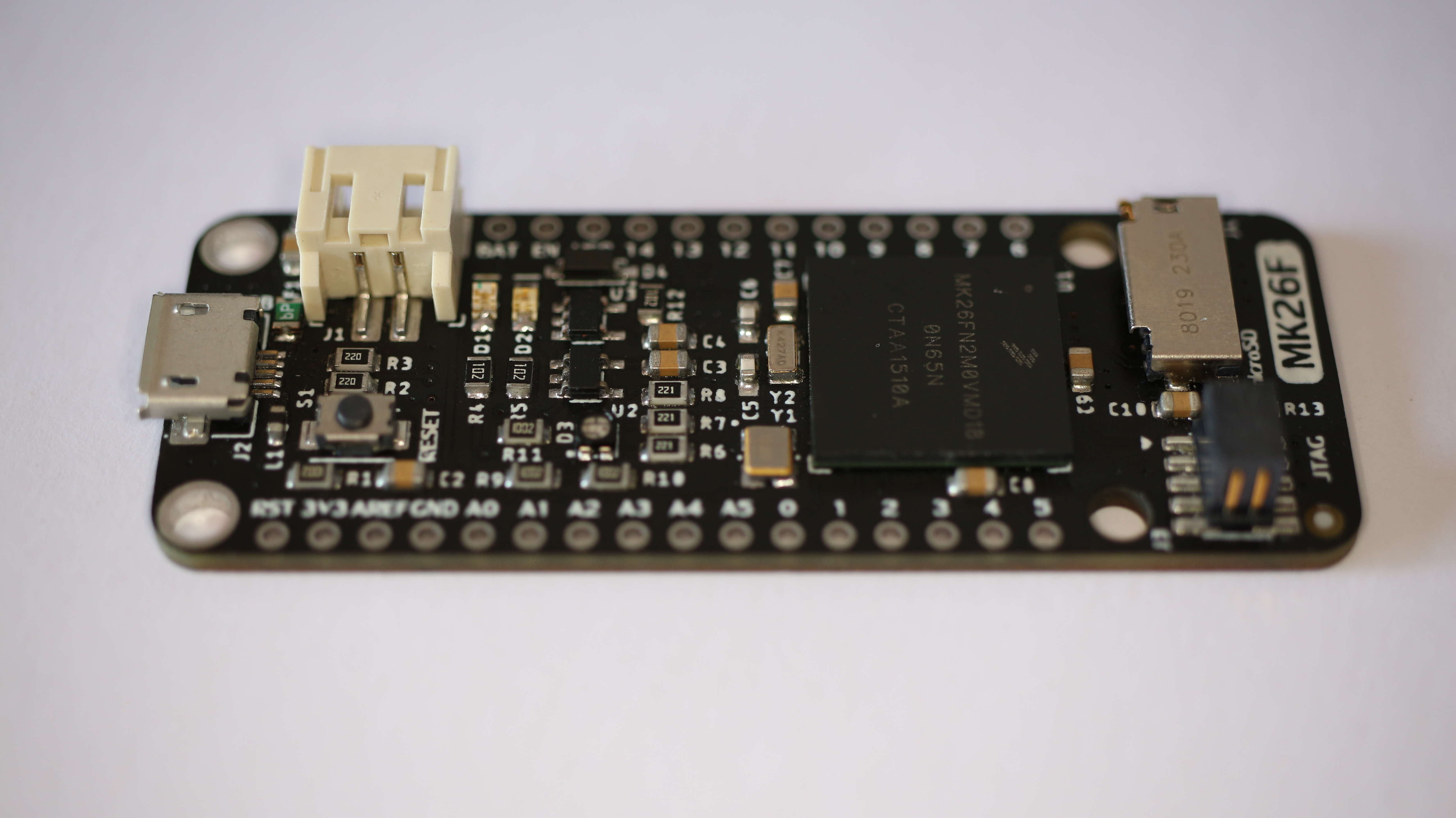
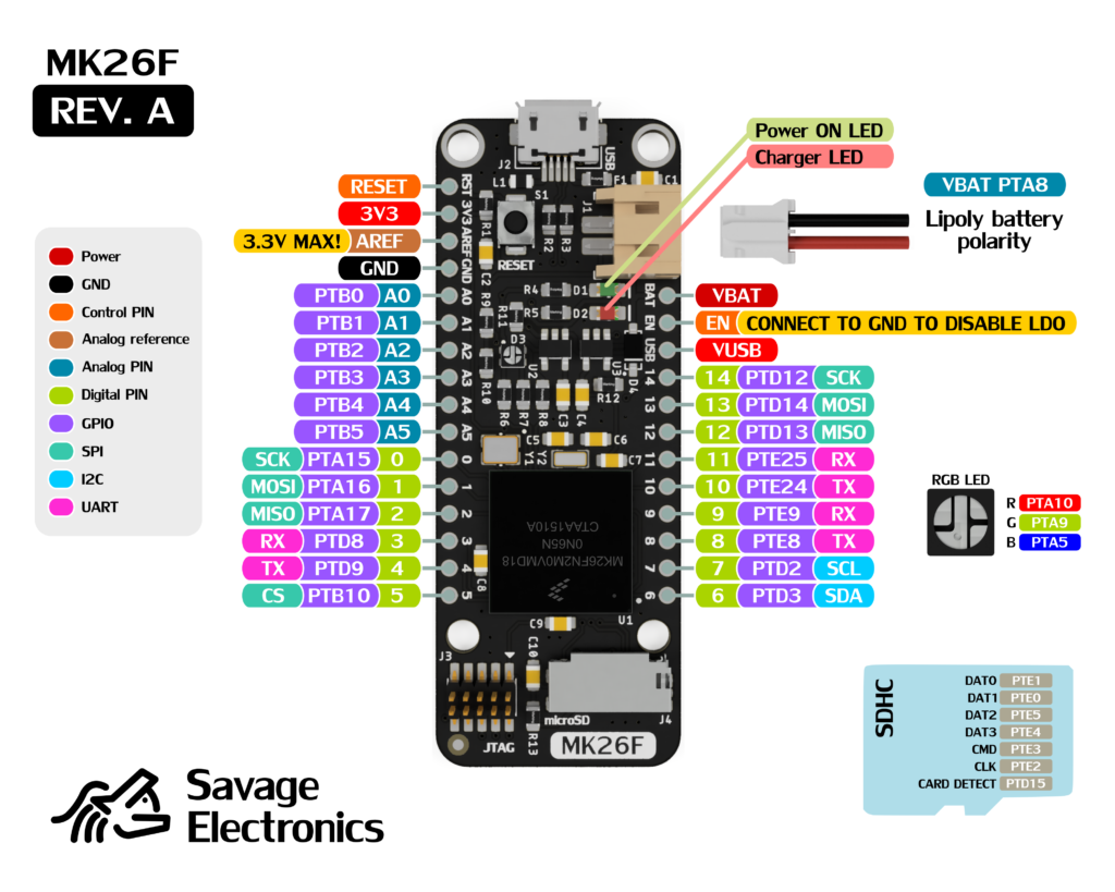
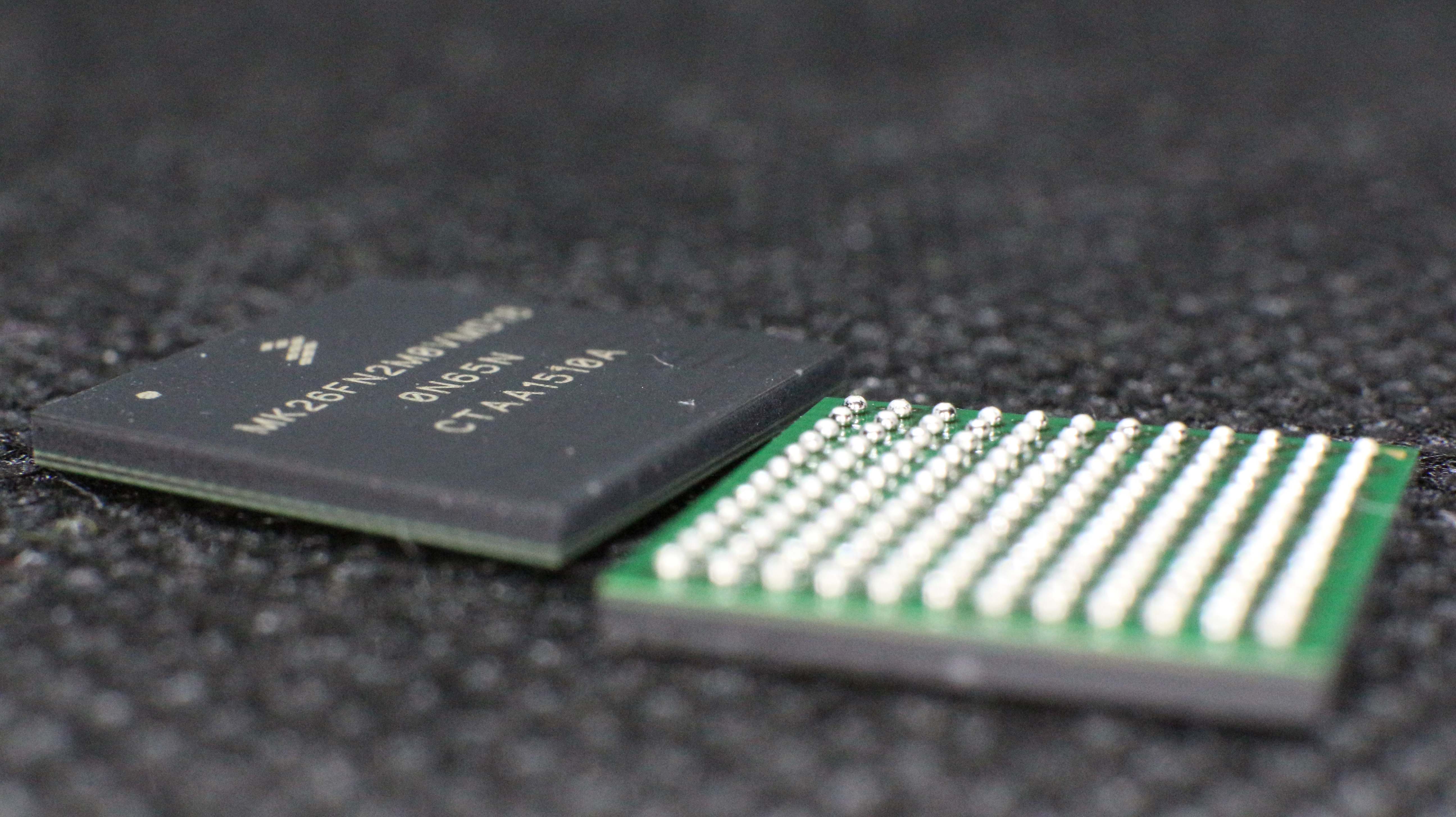
The MK26F Feather is a board that packs the NXP/Freescale MK26F which has an ARM Cortex M4F core at 180Mhz with 2Mb of Flash and 256Kb of RAM, it also has an RGB LED and socket for microSD but with an SDHC interface instead of SPI.
Having the Adafruit Feather format it’s very useful in case that you are working with other microcontrollers with different characteristics and this way it is easy to switch for project capabilities expansion.
I will use these boards with other projects to show you what kind of applications we can do with them. If you are interested you can purchase them at my Tindie Store.
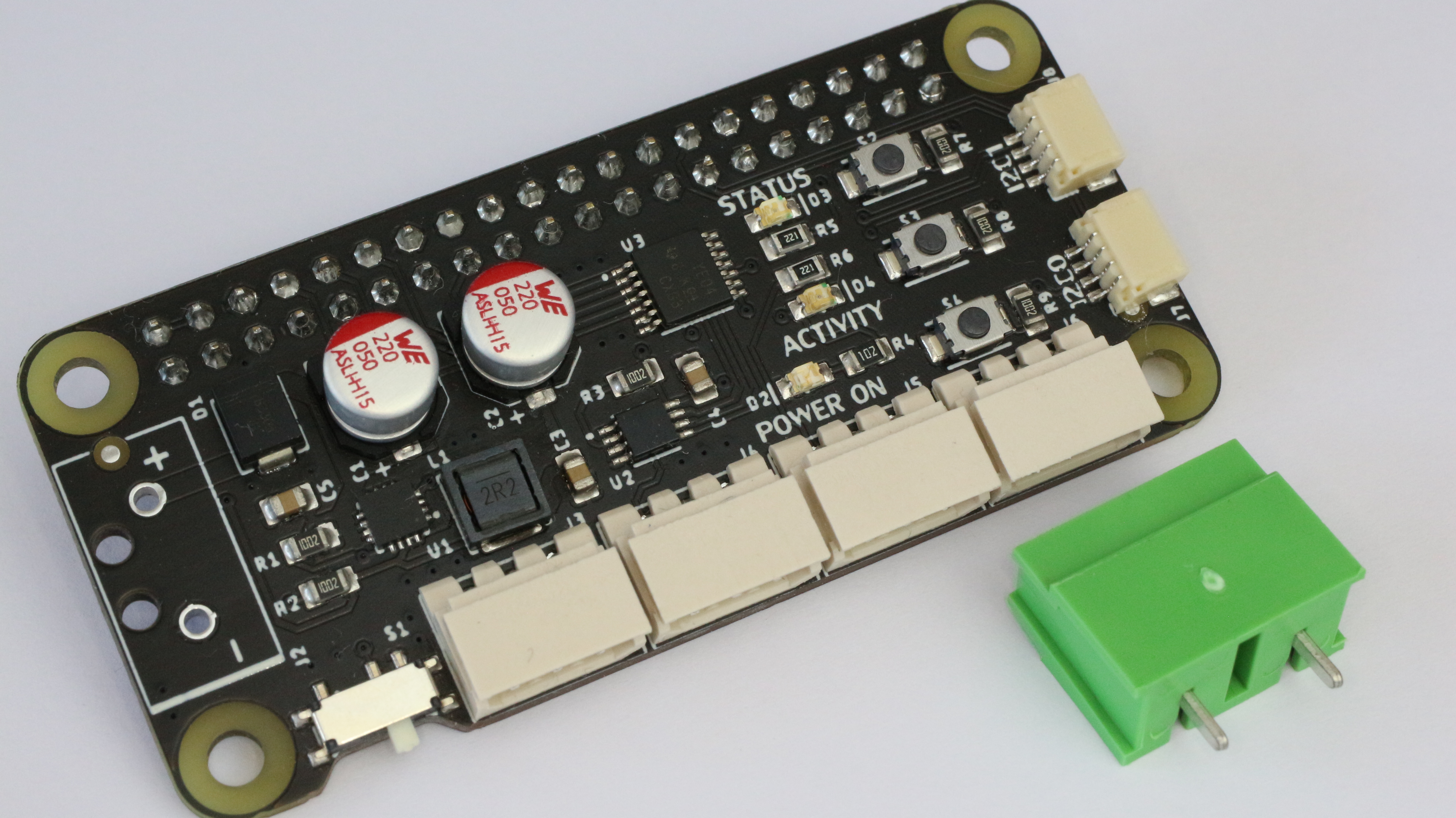
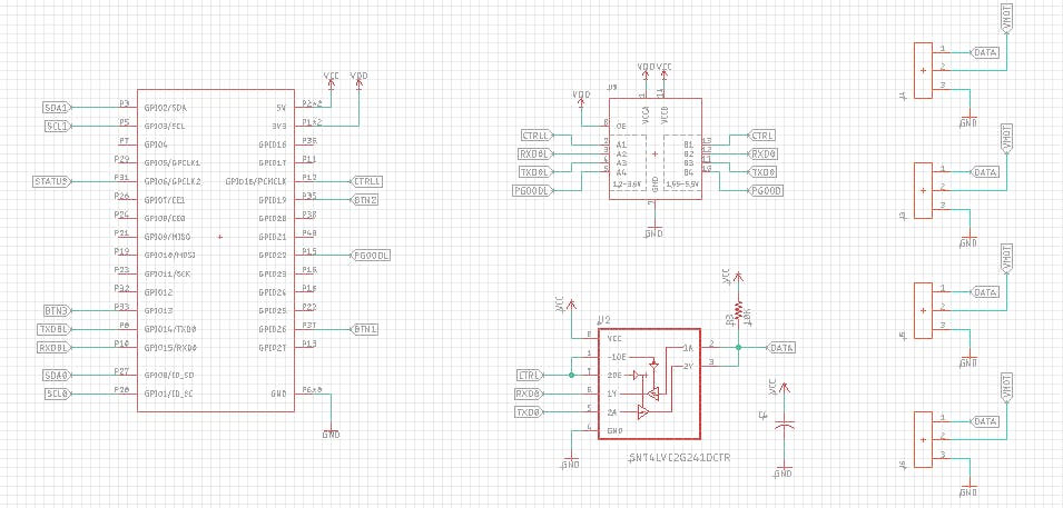
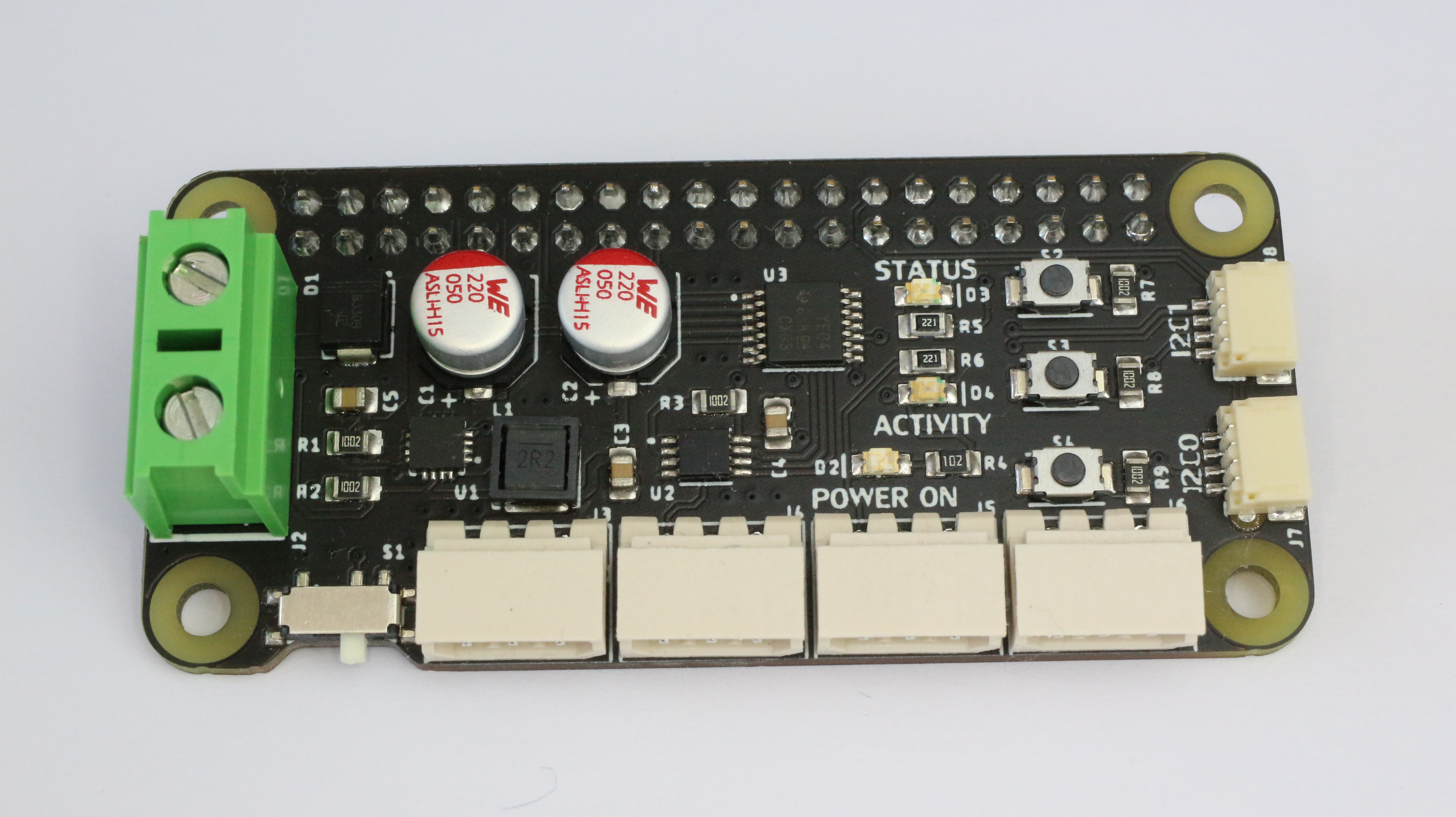
The Dynamixel Hat is a board capable of communicating the raspberry Pi ( Serial ) with the Dynamixel servos by using the 74LS241 Tri-state Buffer connected to 3-pin Molex connectors.
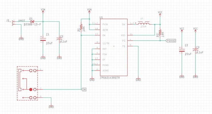
The board contains a TI TPS62143 regulator that steps down the voltage to power up the Raspberry Pi Zero that can be power on or off with the onboard slide switch. The TPS62143 is a synchronous step-down DC-DC converter optimized for applications with high power density.
This board accepts 2S and 3S Lipo batteries, the DC-DC converter accepts up to 17 Volts but the motors recommended voltage is 11.1V ( 3S Lipo ) as the MAX Input voltage is around 16 Volts.
The boards incorporate two I2C ports for sensors for your robotic project. These are JST 1 mm pitch and 4-pin connectors compatible with many boards on the QWIIC family.
There are also 3 LEDs and 3 Buttons for notification and interaction with the electronics, the buttons are programable through the Raspberry GPIOs and 1 LED also GPIO Configurable, the other 2 LEDs are the Activity and PowerOn notification.
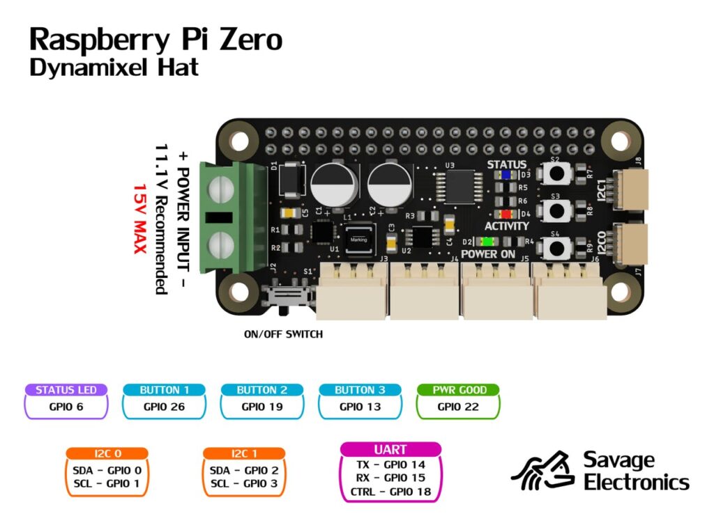
Pinout
Test code:
import RPi.GPIO as GPIO
import serial
import time

GPIO.setwarnings(False)
GPIO.setmode(GPIO.BCM)
GPIO.setup(18,GPIO.OUT)     # Control Data Direction Pin
GPIO.setup(6,GPIO.OUT)      # Blue LED Pin

GPIO.setup(26,GPIO.IN)      # S2 Push Button Pin
GPIO.setup(19,GPIO.IN)      # S3 Push Button Pin
GPIO.setup(13,GPIO.IN)      # S4 Push Button Pin


Dynamixel=serial.Serial("/dev/ttyS0",baudrate=1000000,timeout=0.1, bytesize=8)   # UART in ttyS0 @ 1Mbps


while True:

    if GPIO.input(26):
        GPIO.output(6,GPIO.LOW)
    else:
        GPIO.output(6,GPIO.HIGH)
        GPIO.output(18,GPIO.HIGH)
        Dynamixel.write(bytearray.fromhex("FF FF 01 05 03 1E CD 00 0B"))  # Move Servo with ID = 1 to position 205
        GPIO.output(18,GPIO.LOW)
        startDynamixel = Dynamixel.read()
        startDynamixel = Dynamixel.read()
        idDynamixel = Dynamixel.read()
        lenghtDynamixel = Dynamixel.read()
        errorDynamixel = Dynamixel.read()
        chkDynamixel = Dynamixel.read()
        print("Servo ID = " , int.from_bytes(idDynamixel,byteorder='big') , " Errors = ", int.from_bytes(errorDynamixel,byteorder='big'))
        time.sleep(1)

    if GPIO.input(19):
        GPIO.output(6,GPIO.LOW)
    else:
        GPIO.output(6,GPIO.HIGH)
        GPIO.output(18,GPIO.HIGH)
        Dynamixel.write(bytearray.fromhex("FF FF 01 04 02 2A 01 CD"))   # Read Voltage of Servo with ID = 1
        GPIO.output(18,GPIO.LOW)
        startDynamixel = Dynamixel.read()
        startDynamixel = Dynamixel.read()
        idDynamixel = Dynamixel.read()
        lenghtDynamixel = Dynamixel.read()
        errorDynamixel = Dynamixel.read()
        voltDynamixel = Dynamixel.read()
        chkDynamixel = Dynamixel.read()
        print("Servo Voltage = " , int.from_bytes(voltDynamixel,byteorder='big'))
        GPIO.output(18,GPIO.HIGH)
        Dynamixel.write(bytearray.fromhex("FF FF 01 04 02 2B 01 CC"))   # Read Temperature of Servo with ID = 1
        GPIO.output(18,GPIO.LOW)
        startDynamixel = Dynamixel.read()
        startDynamixel = Dynamixel.read()
        idDynamixel = Dynamixel.read()
        lenghtDynamixel = Dynamixel.read()
        errorDynamixel = Dynamixel.read()
        tempDynamixel = Dynamixel.read()
        chkDynamixel = Dynamixel.read()
        print("Servo Temperature = " , int.from_bytes(tempDynamixel,byteorder='big'))
        GPIO.output(18,GPIO.HIGH)
        Dynamixel.write(bytearray.fromhex("FF FF 01 04 02 24 02 D2"))   # Read Position of Servo with ID = 1
        GPIO.output(18,GPIO.LOW)
        startDynamixel = Dynamixel.read()
        startDynamixel = Dynamixel.read()
        idDynamixel = Dynamixel.read()
        lenghtDynamixel = Dynamixel.read()
        errorDynamixel = Dynamixel.read()
        posDynamixel = Dynamixel.read(2)
        chkDynamixel = Dynamixel.read()
        print("Servo Position = " , int.from_bytes(posDynamixel,byteorder='little'))
        time.sleep(1)

    if GPIO.input(13):
        GPIO.output(6,GPIO.LOW)
    else:
        GPIO.output(6,GPIO.HIGH)
        GPIO.output(18,GPIO.HIGH)
        Dynamixel.write(bytearray.fromhex("FF FF 01 05 03 1E 32 03 A3"))    # Move Servo with ID = 1 to position 816
        GPIO.output(18,GPIO.LOW)
        startDynamixel = Dynamixel.read()
        startDynamixel = Dynamixel.read()
        idDynamixel = Dynamixel.read()
        lenghtDynamixel = Dynamixel.read()
        errorDynamixel = Dynamixel.read()
        chkDynamixel = Dynamixel.read()
        print("Servo ID = " , int.from_bytes(idDynamixel,byteorder='big') , " Errors = ", int.from_bytes(errorDynamixel,byteorder='big'))
        time.sleep(1)
Enable UART at 1Mbps in your Raspberry Pi Zero
Make sure to add the following to your Raspberry config file at /boot/config.txt:
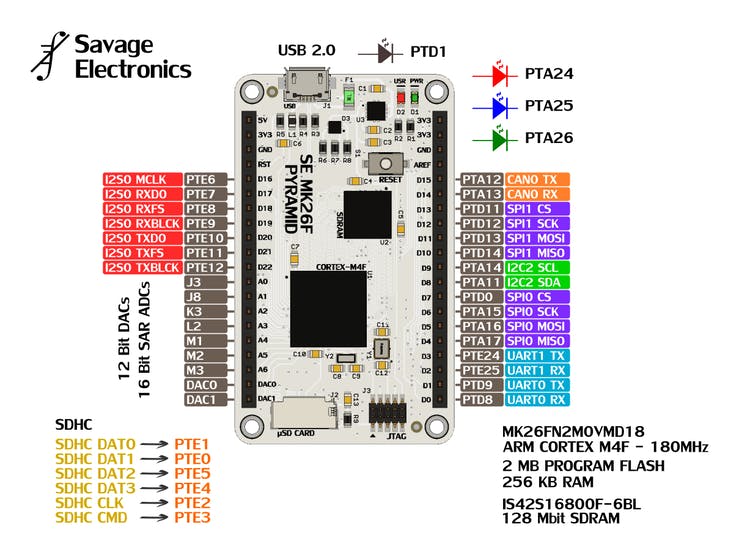
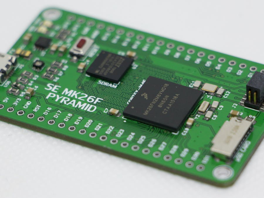
I personally like to work with NXP/Freescale microcontrollers, and that is why I have designed a development board with the intention to also expand to other brands of microcontrollers.
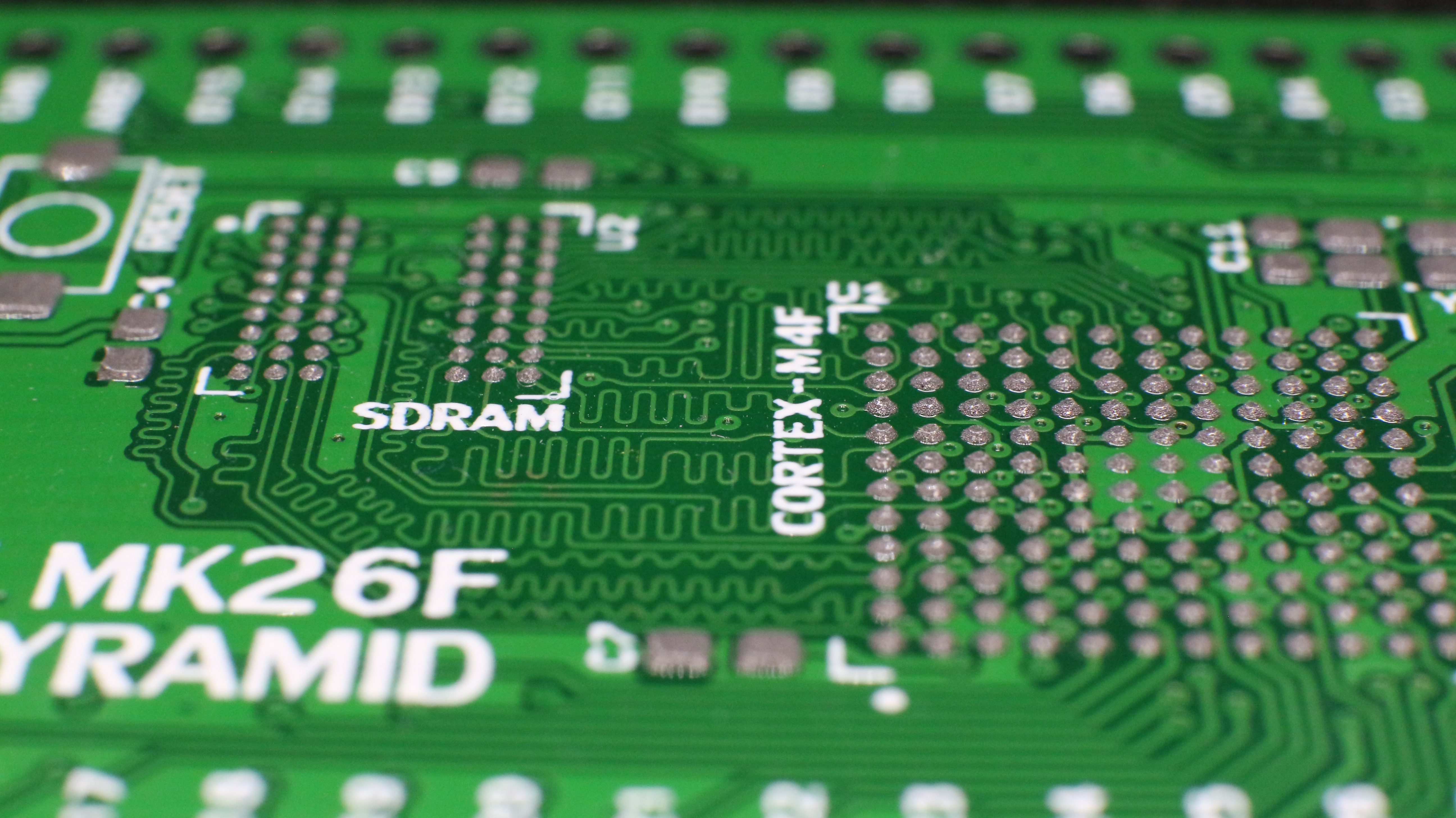
I have called this board a Pyramid, stating with the MK26F2M0VMD18 which come in a BGA144 footprint with a pitch between balls of 1mm, This MCU is a very nice microcontroller as its an ARM Cortex M4F with a CPU clock of 180Mhz in the High-Speed mode configuration with 2MB of Flash memory and 256Kb of SRAM. The board that I have designed includes an SDRAM of 16MB and an SDHC socket for SD Cards.
This board also includes a USB2.0 Host connector a couple of notification LEDs and an RGB LED. The board can be programmed through the JTAG/SWD port or by installing a USB Bootloader.
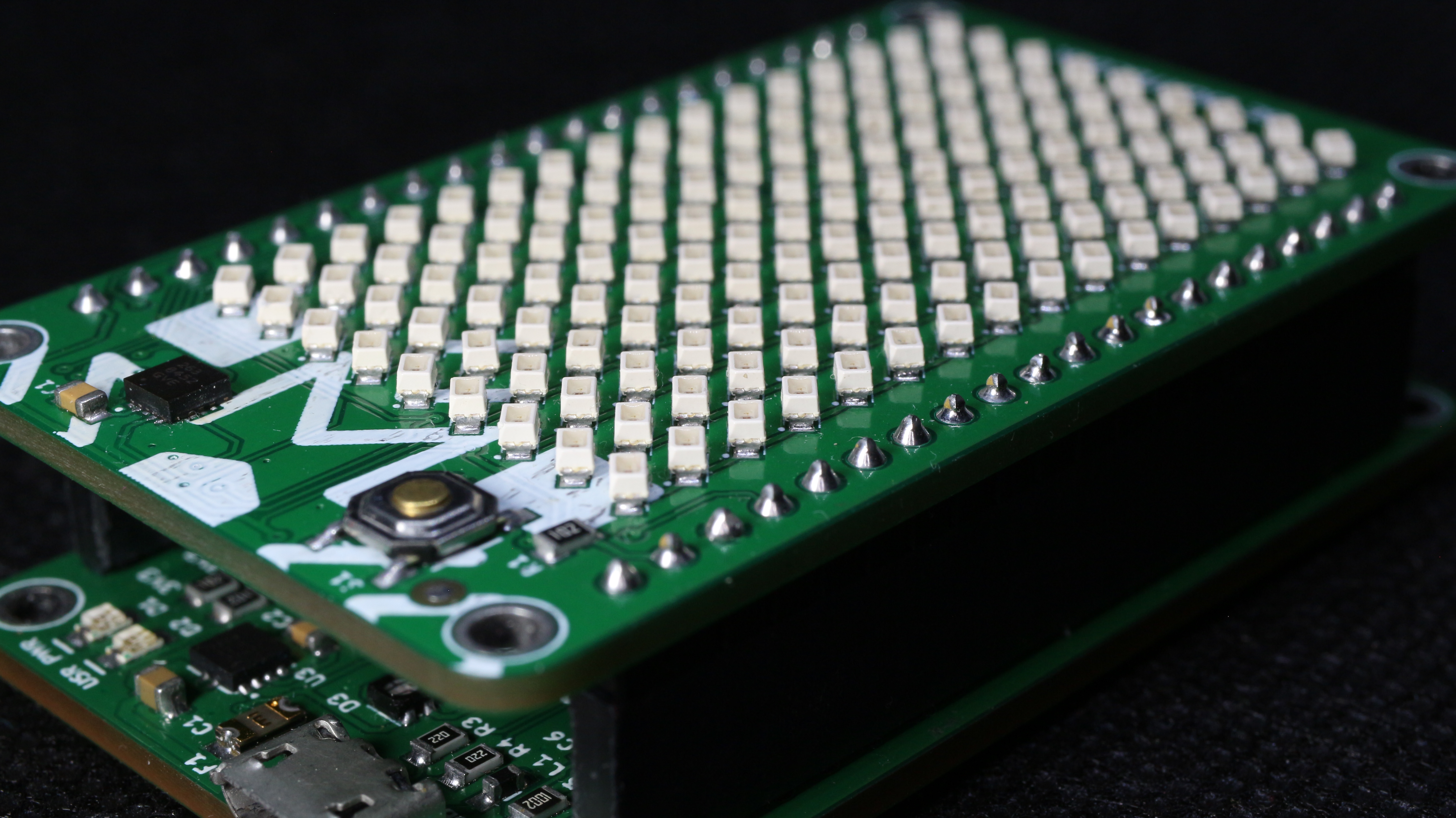
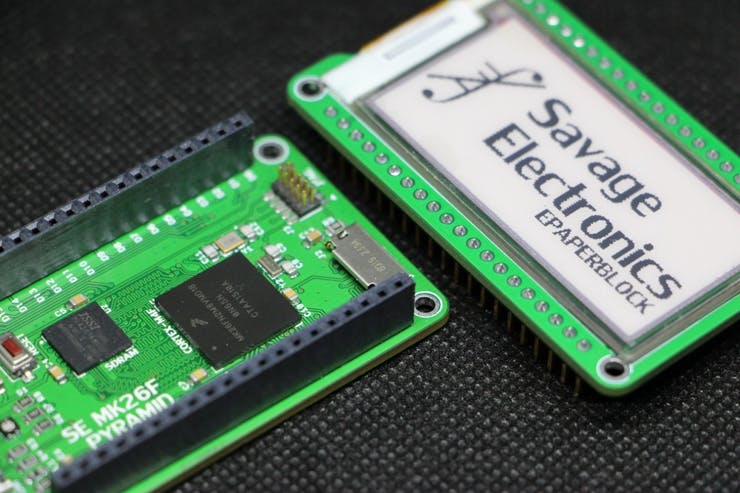
To this development board, I have also designed some boards called Blocks that will be swappable between the other brand MCU Pyramids.
If you are interested in this project please let me know in the comments section below.
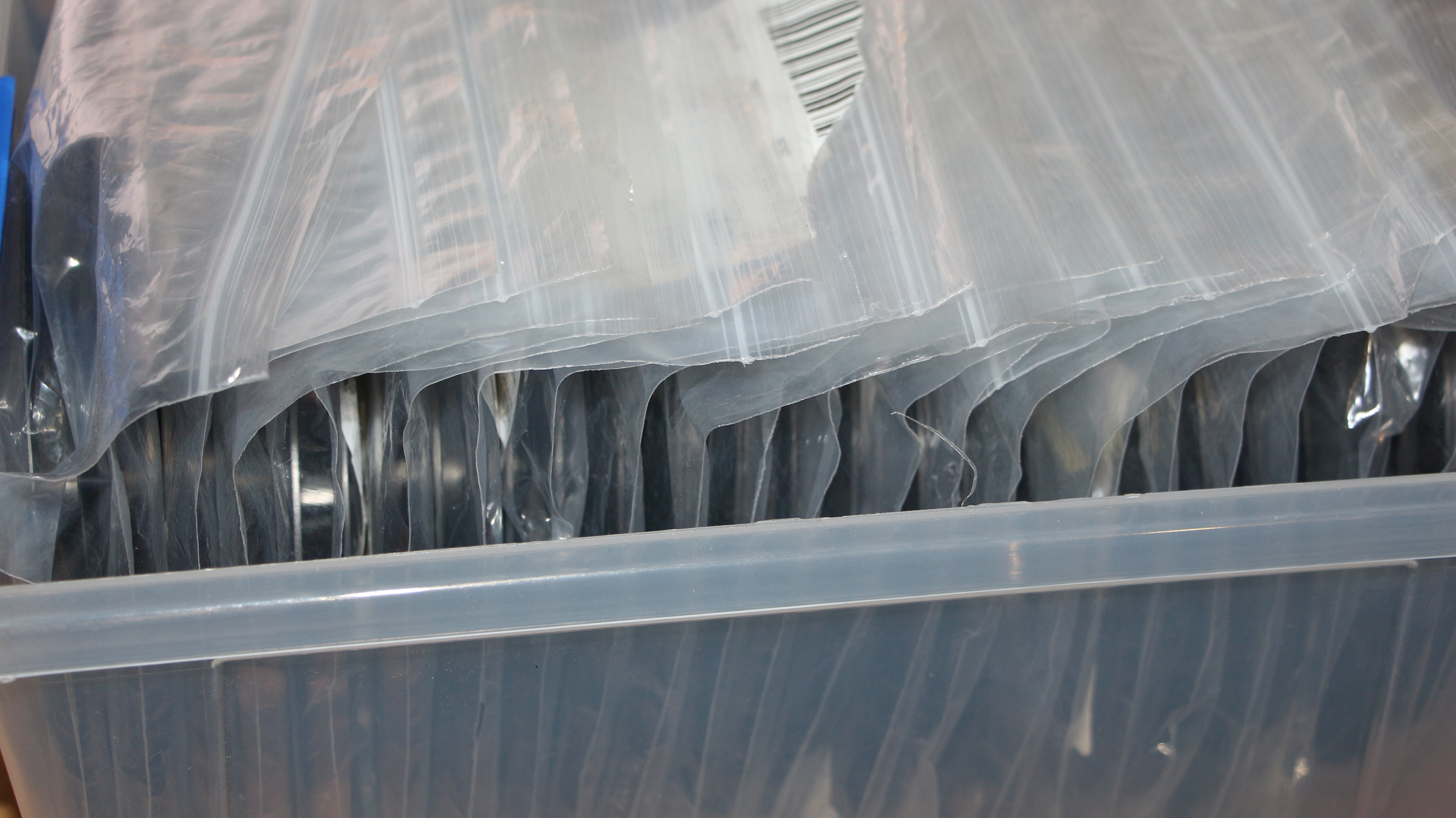
There are some times when I am in need of a resistor, or a single LED or capacitor and the cost of 500 or 1000 of them are incredibly cheap, under a dollar, so when I caught that kind of offer I do not think it twice, these components usually are shipped in reels inside a bag and they are very inefficient space-wise so looking into the internet I have found a system that allows easy handling.
SMD components reels
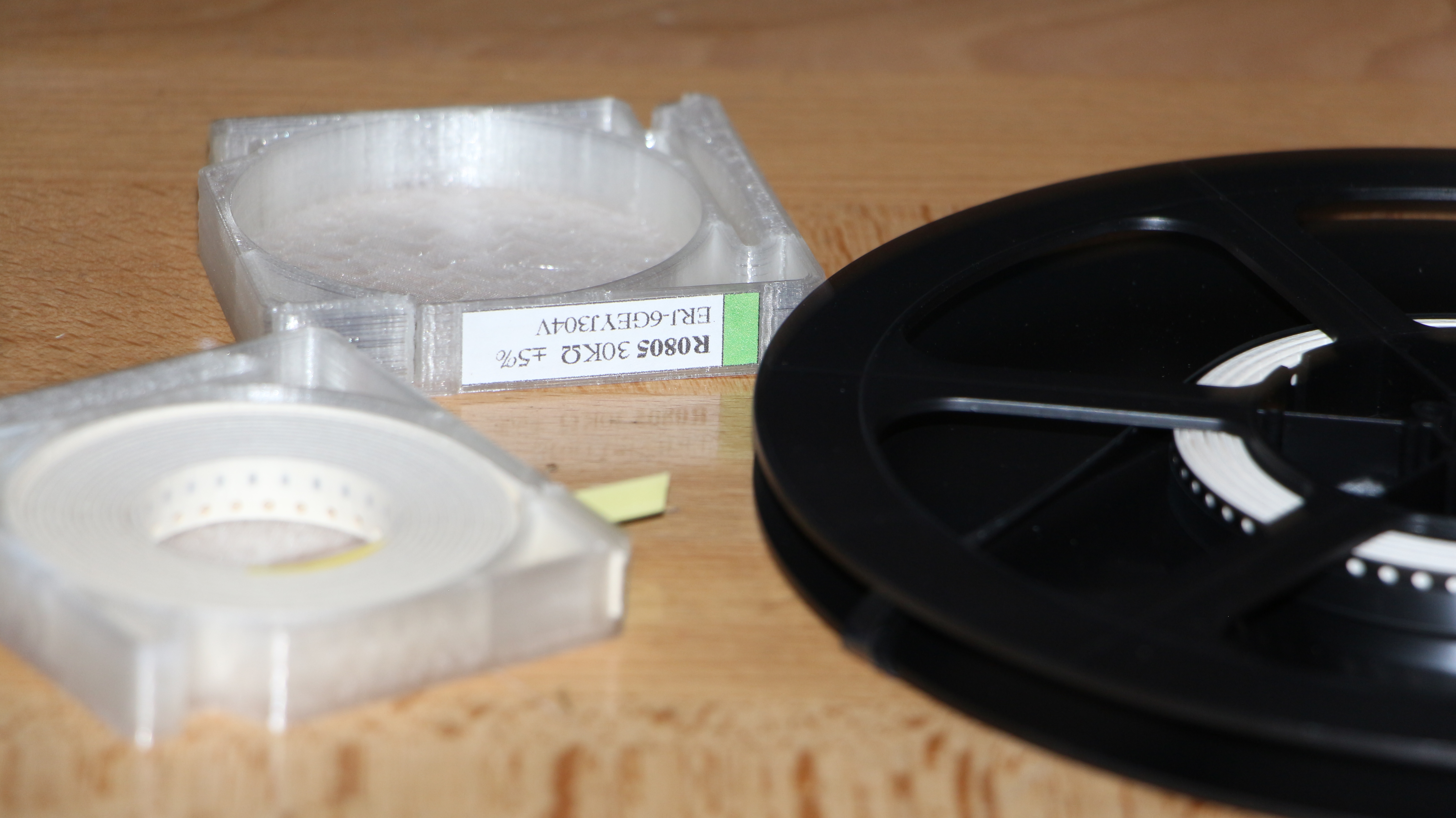
I have re-spinned the original design that does not need any kind of metal spring, bearings, and screws. It’s easy to replace those components with the properties of plastic when you have access to a 3D printer.
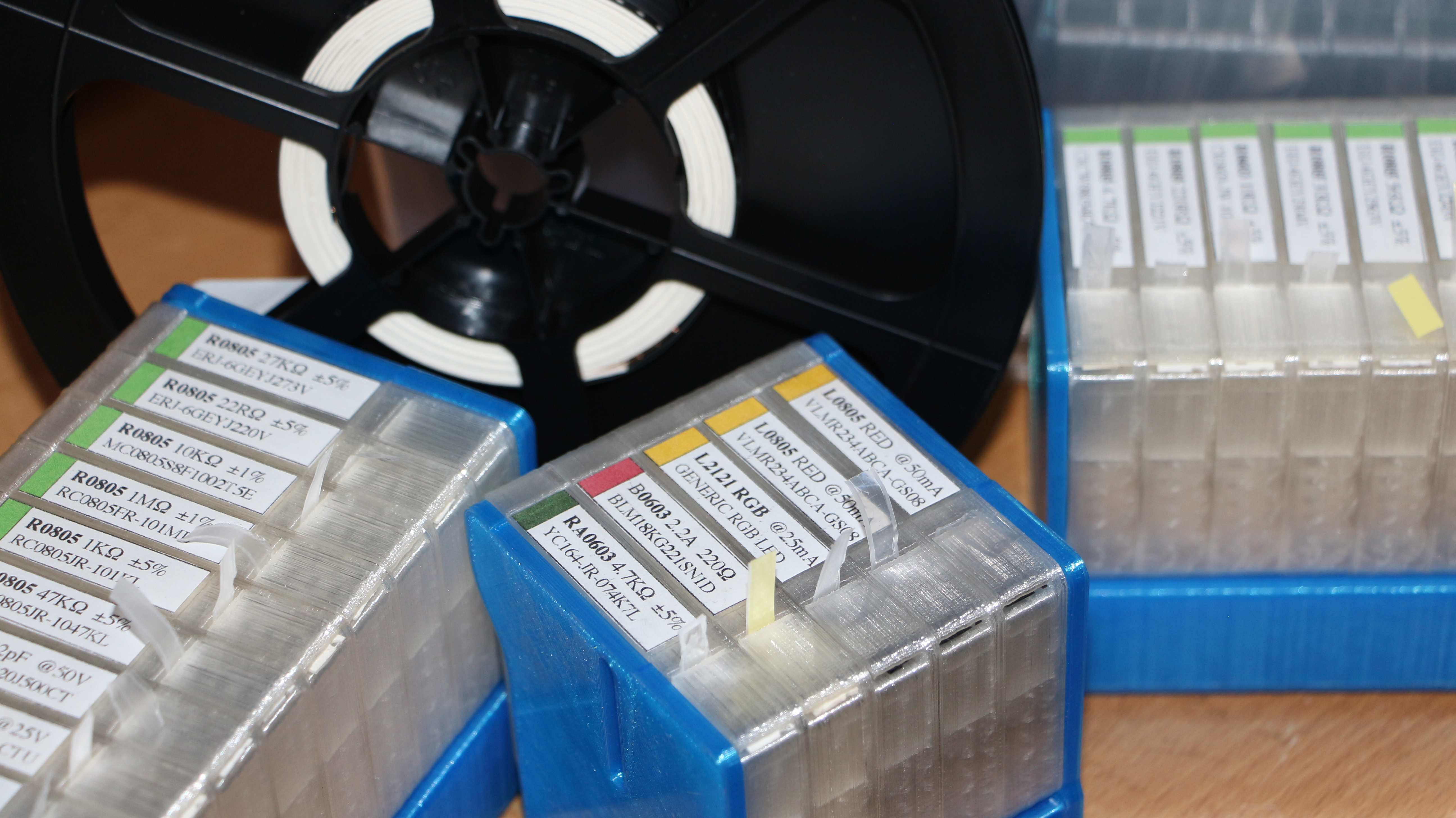
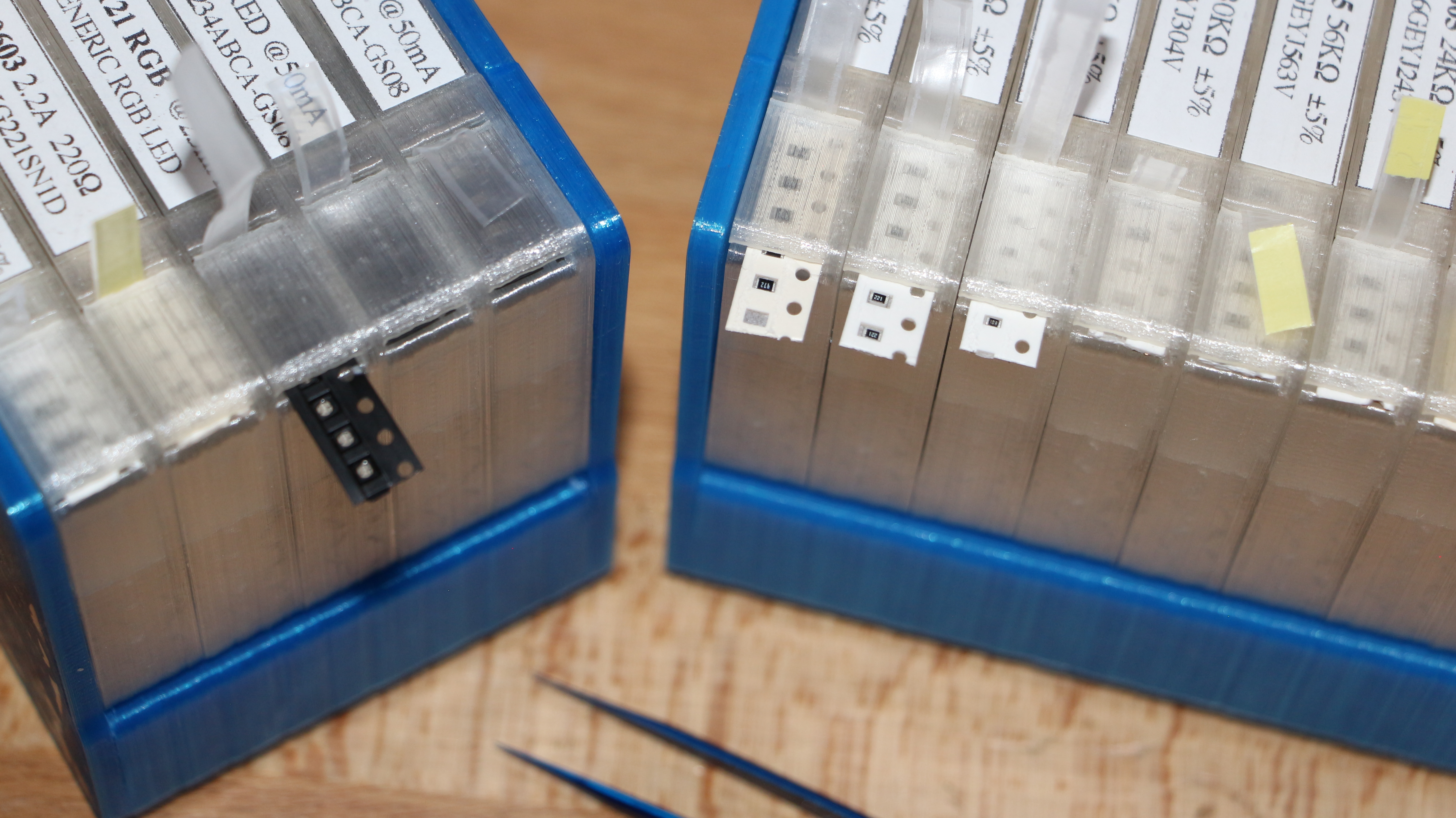
SMD reel to 3D printed cassetes
The cassettes are very easy to print and are very useful when you are starting to make your own collection of SMD parts.
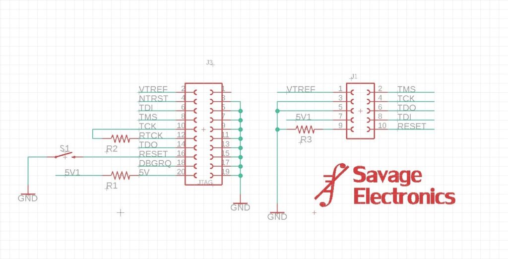
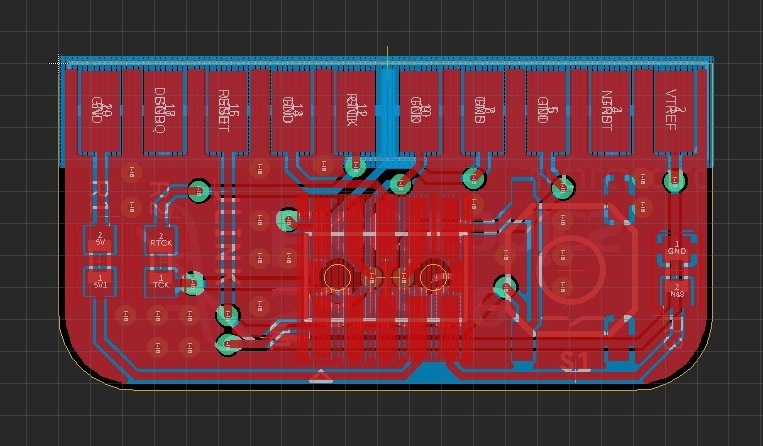
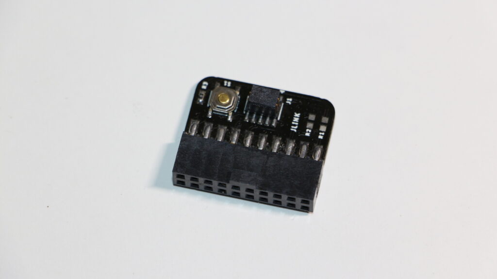
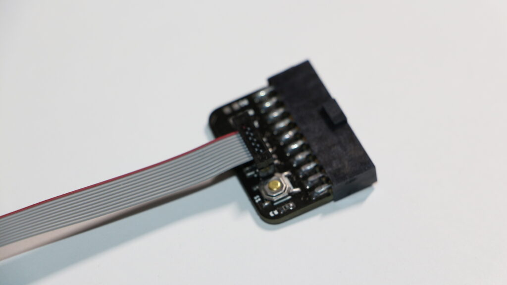
If you ever wanted to reduce the footprint of your programming interface a good option is to use the SWD port to program your microcontroller instead of the 20 pin JTAG connector, most development boards use the 10 Pin 1.27 mm pitch SWD connector so I design a J-link Segger adaptor board to SWD.
JTAG Adapter board
The schematic is very simple as it just re-routes the SWD signals of the SWD, so I have also connected the other JTAG signal to make a reduced footprint JTAG.
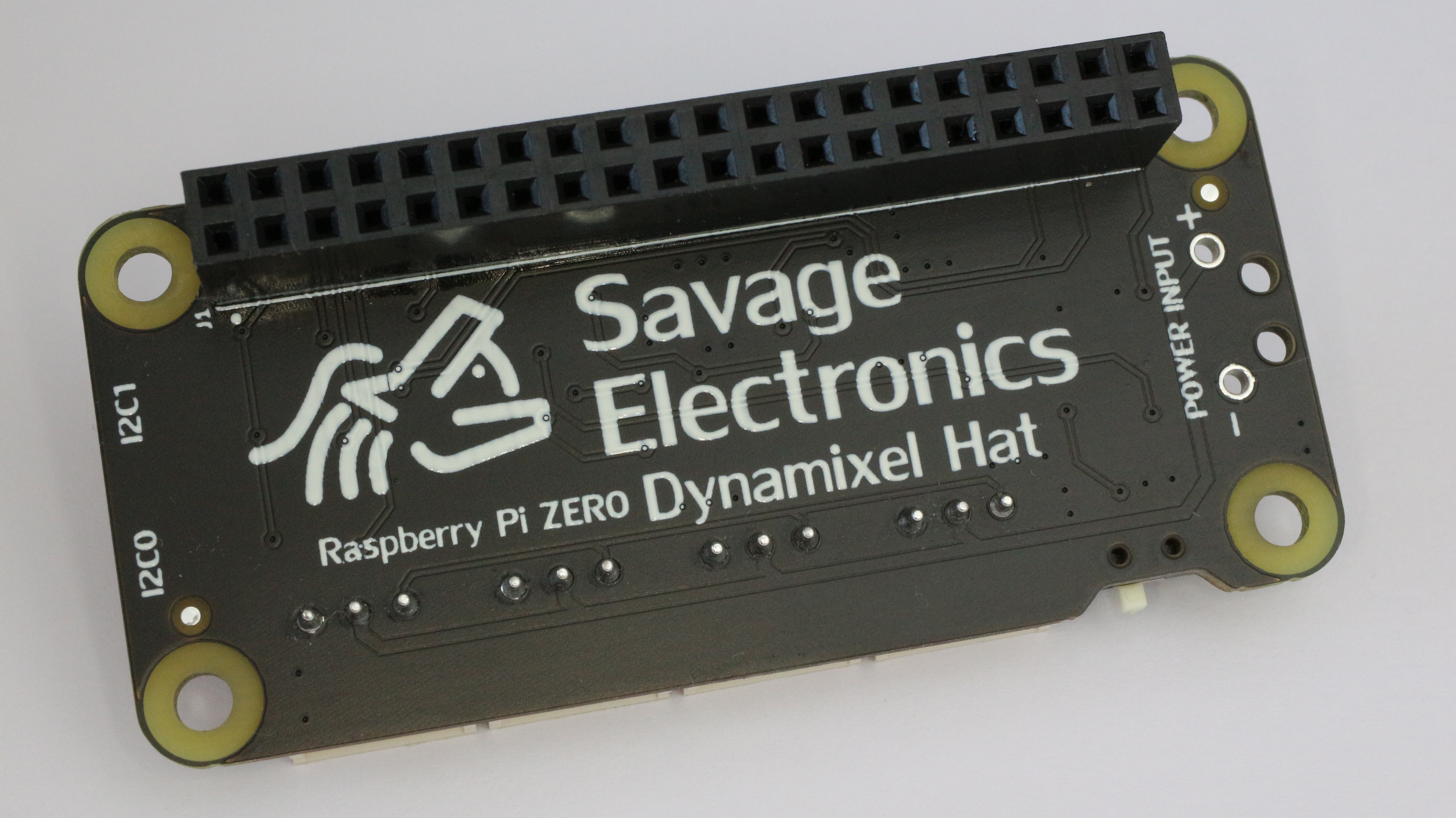
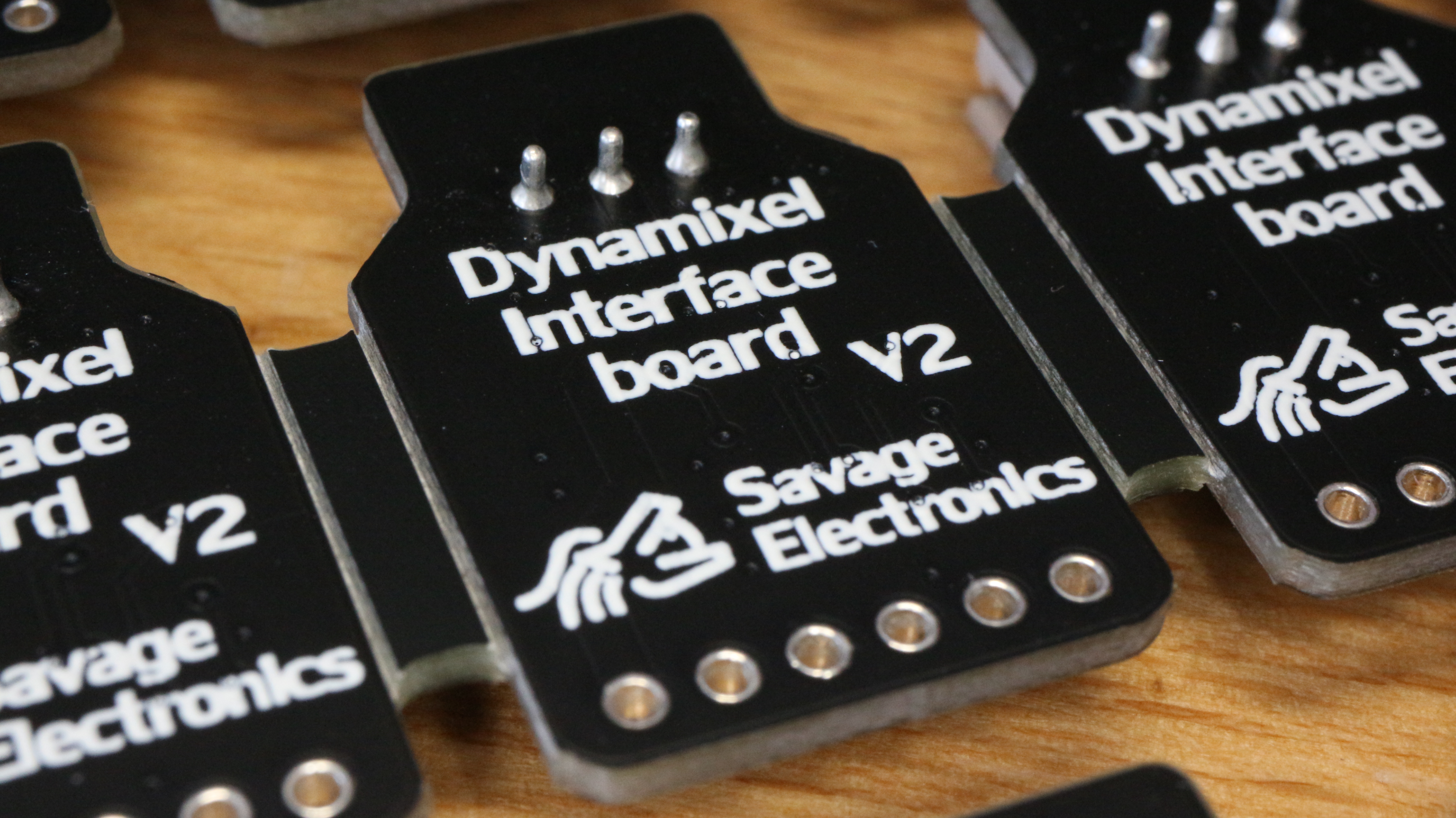
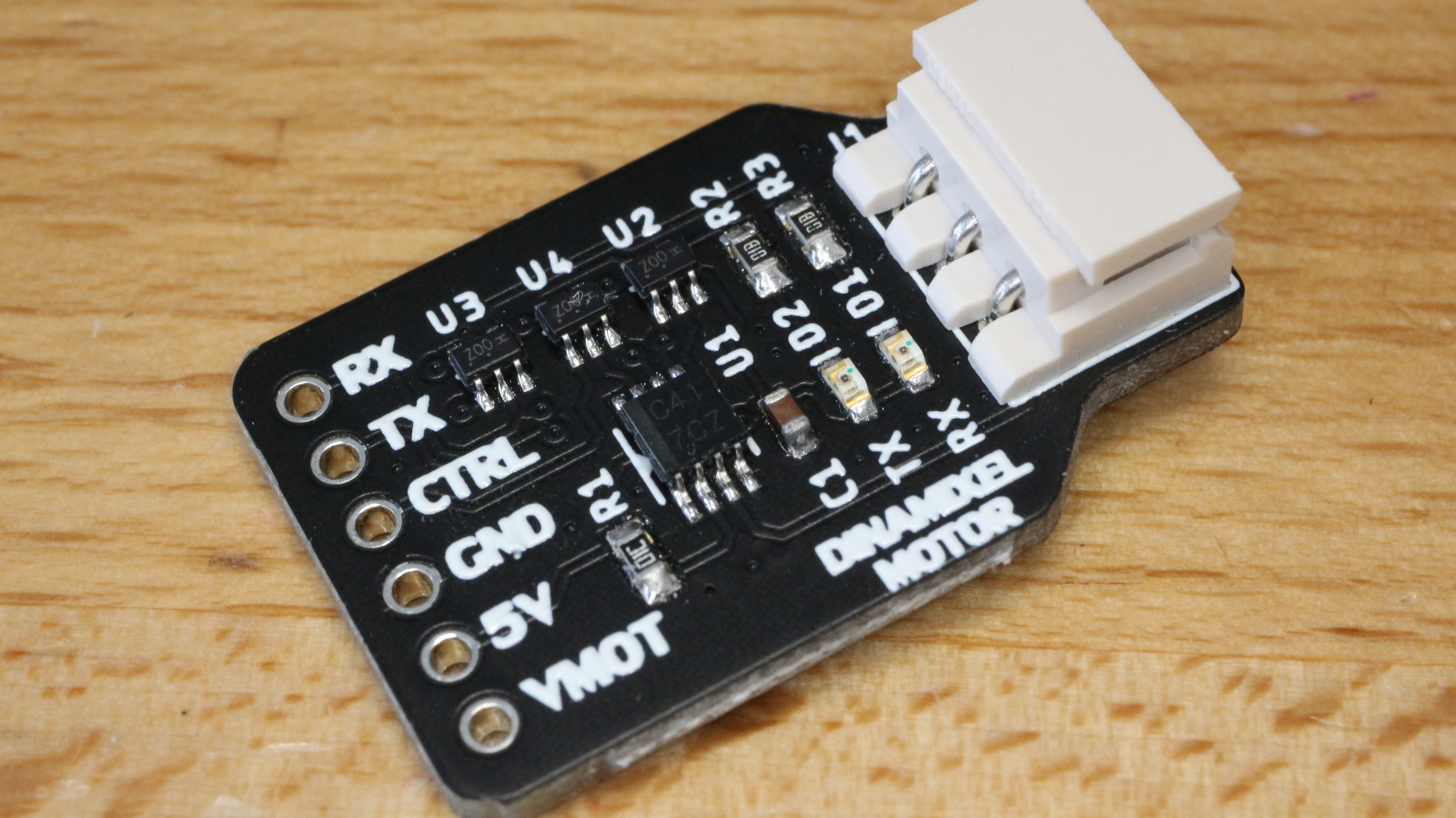
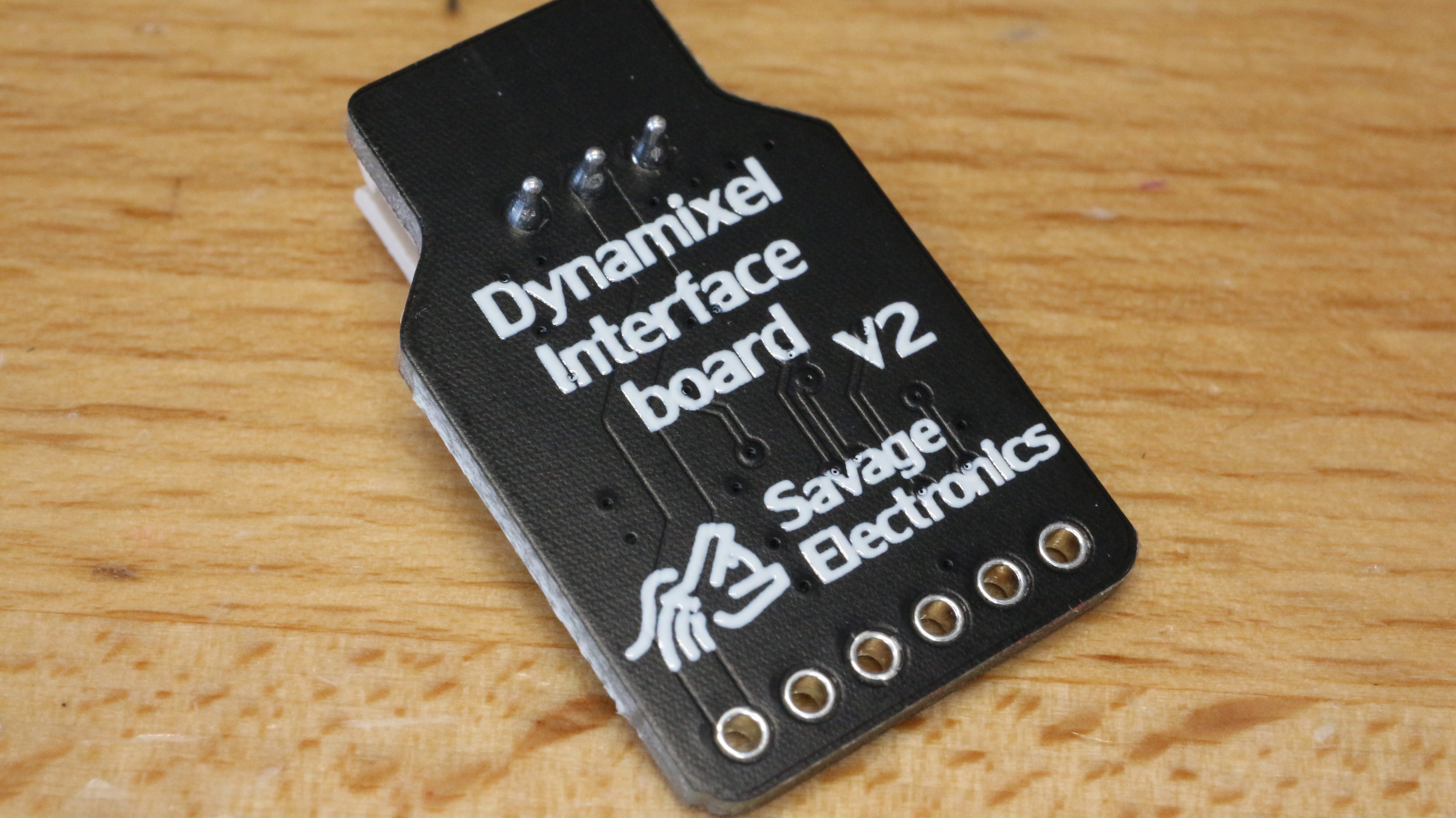
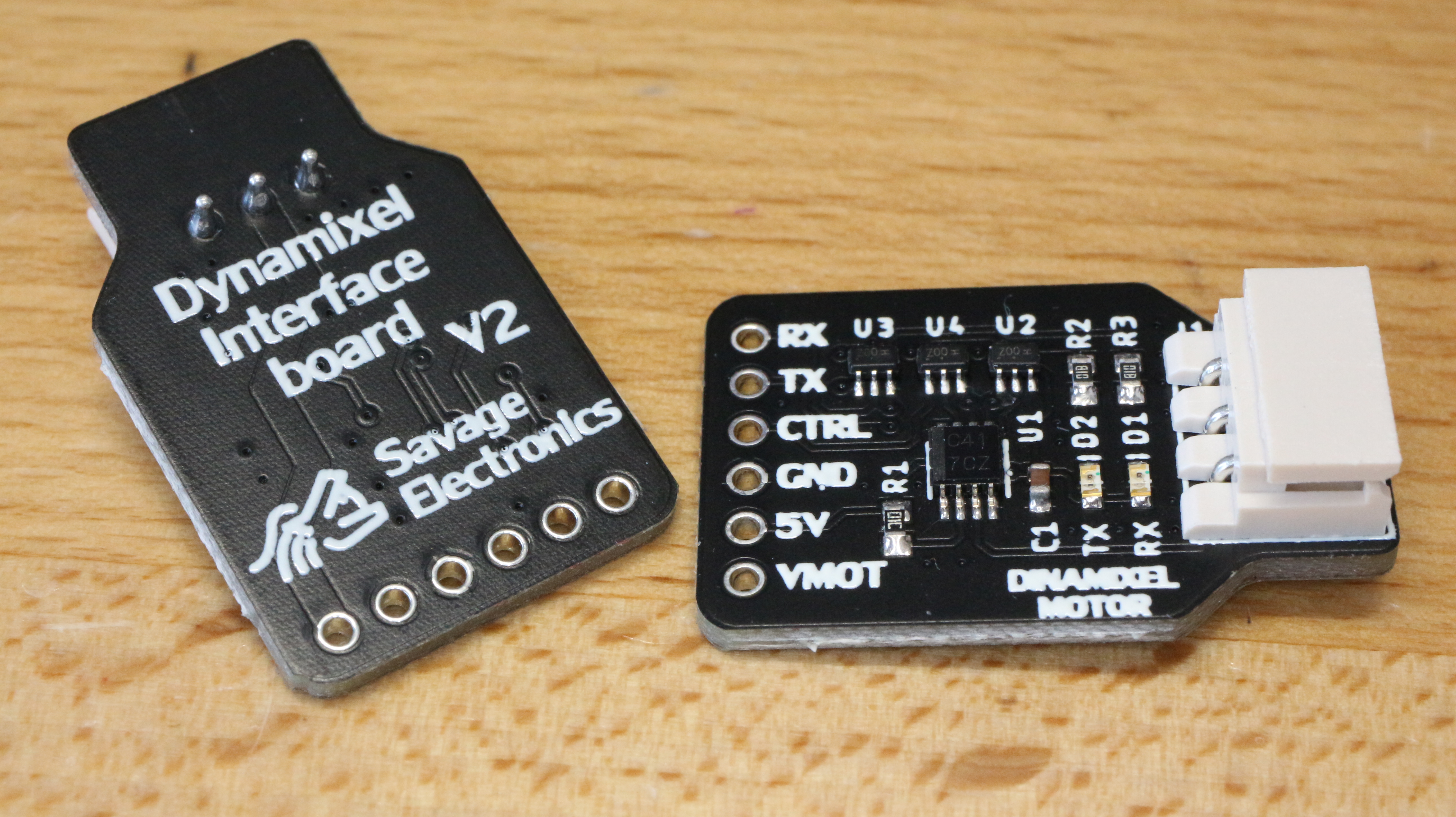
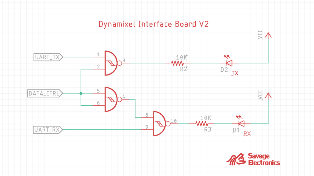
I have decided to redesign the Dynamixel interface and put it again in stock on my Tindie store, this redesign include some status LEDs that visually let you know if the motor is communicating to the motors and vice-versa, I have also decided to change the connector orientation which makes the board a little bit compact and more compatible with small dimensions projects.
The circuit for the LED indicators uses some NAND gates that let the user know when data is going to the servo and from the servo to the microcontroller without the need for a logic analyzer.
This update is a very simple update and it does not affect the functionality of the interface, it is just a visual benefit for the user.
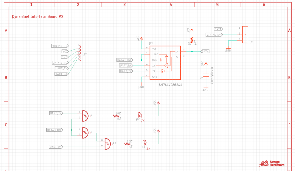
Here is the schematic in case you have the components and wish to make your own interface.
Test code:
#include <DynamixelSerial.h>

#define SERVO_ID  1
int Temperature,Voltage,Position;

void setup(){
Dynamixel.setSerial(&Serial1); // &Serial - Arduino UNO/NANO/328P, &Serial1, &Serial2, &Serial3
Dynamixel.begin(1000000,2);    // Inicialize the servo at 1 Mbps and Pin Control 2
Serial.begin(9600);            // Begin Serial Comunication
}

void loop(){
  Temperature = Dynamixel.readTemperature(SERVO_ID); // Request and Print the Temperature
  Voltage = Dynamixel.readVoltage(SERVO_ID);         // Request and Print the Voltage
  Position = Dynamixel.readPosition(SERVO_ID);       // Request and Print the Position

  Dynamixel.move(1,random(200,800));

  Serial.print("Temperature: ");                  // Print the variables in the Serial Monitor
  Serial.print(Temperature); Serial.print(" celcius, ");
  Serial.print("Voltage: ");
  Serial.print(float(Voltage)/10);Serial.print(" volts, ");
  Serial.print("Position: ");
  Serial.println(Position);

  delay(1000);
}
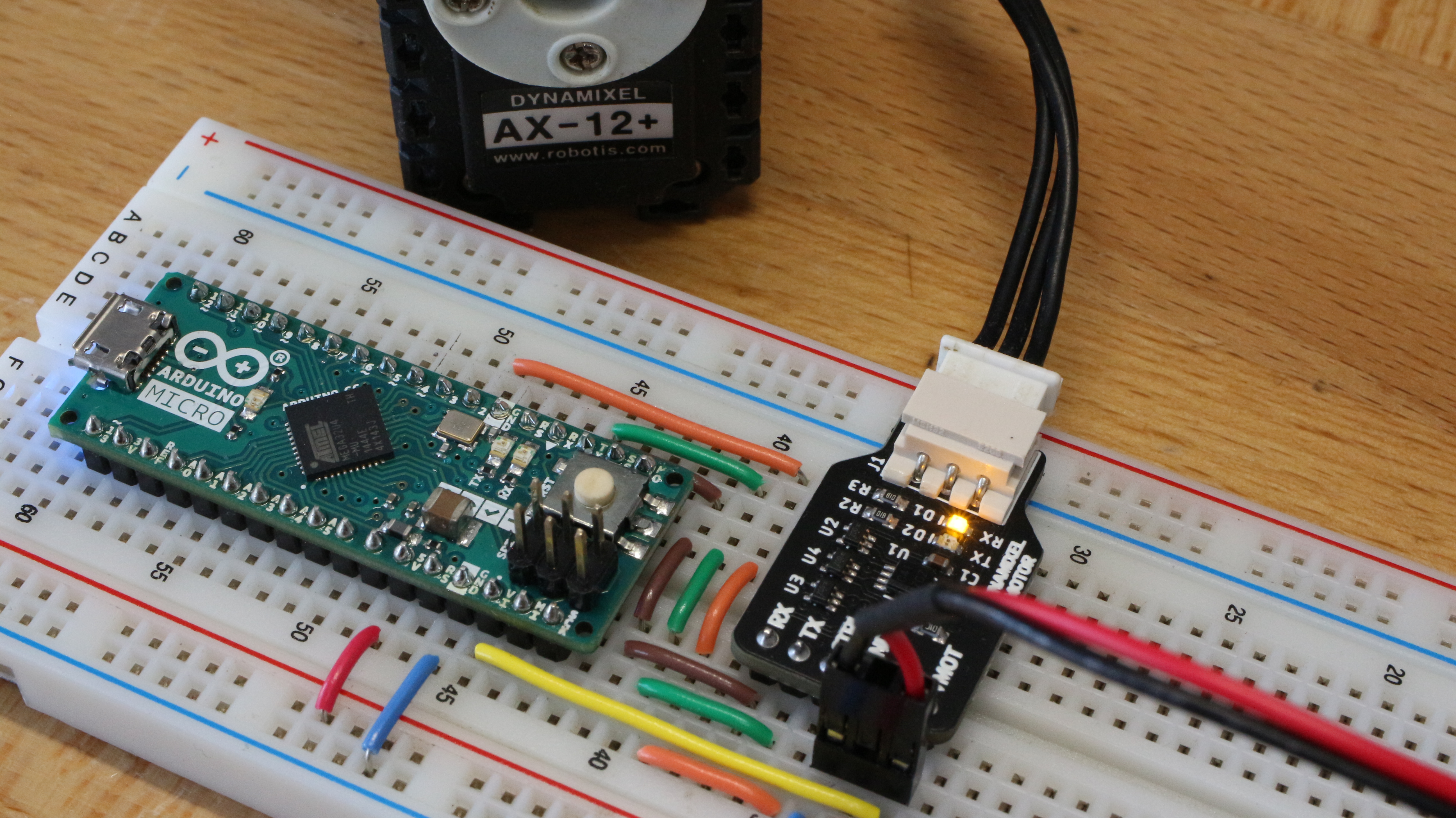
After a long time here is an update in the Library for Dynamixel Sero Motors as the AX-12A.
These servos are pretty awesome, they seem the perfect solution for robotics as they can return several parameters as internal temperature, the voltage of operation, position, speed, torque, and all of this is accomplished as they have an internal microcontroller, the Atmega8 from Atmel which communicates over Half-Duplex UART TTL. This library helps you communicate with the Dynamixel Servos protocol V1.0 in any of the Serial channels of your Arduino.
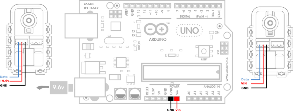
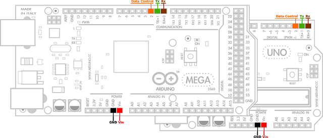
The voltage of operation of these motors is recommended to be 11.1 volts, but it should work ok from 6V to 14V as the datasheet describes in the electrical ratings. Don’t forget to join the grounds of your motor’s power supply and the one from the microcontroller in other to level the signal voltage between them.
Power supply connectionArduino UART pins connection
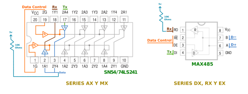
In order for this library to work and to ensure proper usage it is necessary to use a tri-state buffer IC, this can be achieved with a 74HC04 NOT gate and a 74HC126 tri-state buffer ICs ad Robotis suggests. I personally prefer the 74LS241 tri-state buffer with inverted enable pin input as is easy to connect and offers the same configuration in a single IC.
Don’t forget the VCC and GND IC power supply connections, VCC should be 5V