Arduino

nRF52832 PRO Panel

This is a new project using the nRF52832 BLE MCU as a very versatile development platform that will allow me to do many projects that requires a connection over Bluetooth and also can perform actions to control basic systems, as data acquisition, data display, motor control, graphical interfaces and much more.

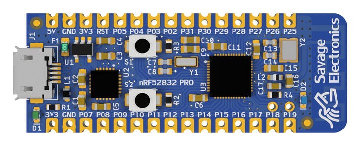
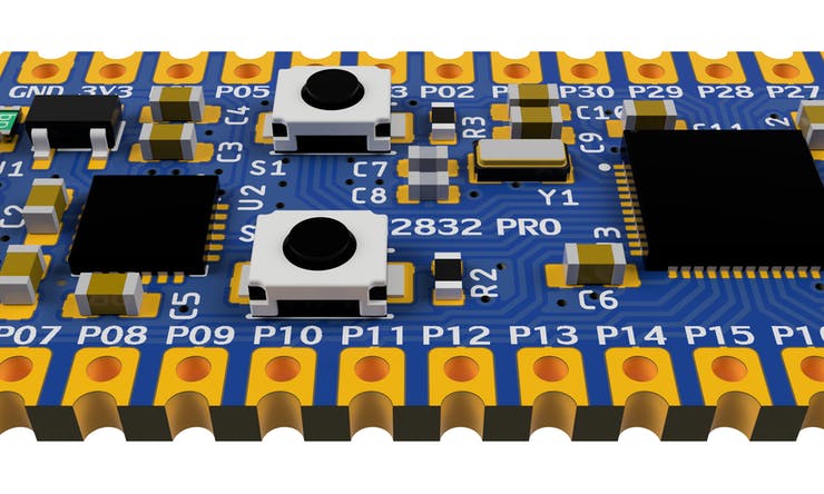
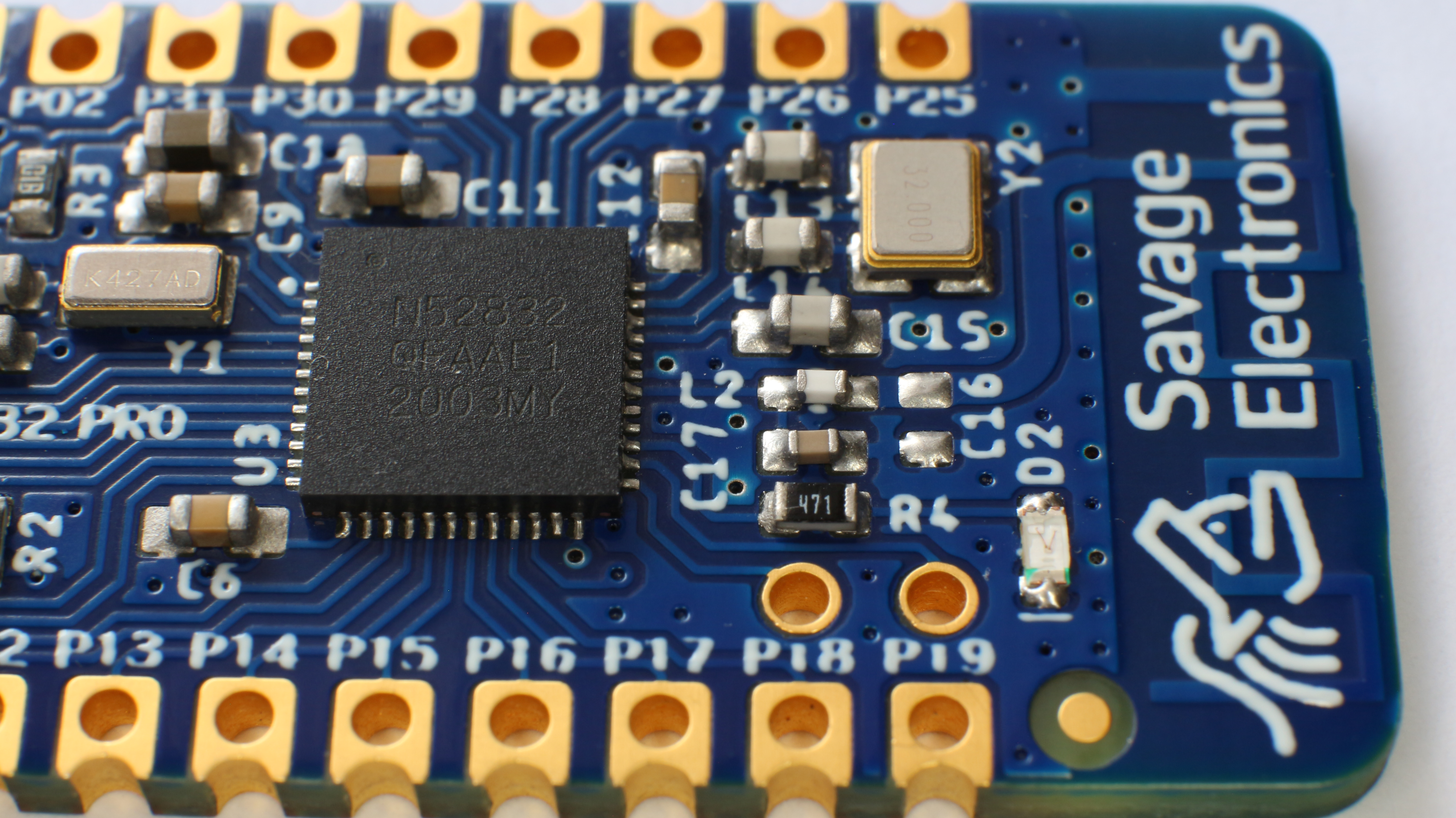
This board dimension is 48x18mm with 30 castellated holes on the side, a micro USB connector for power, and programming through a USB to serial converter CP2104, two tactile switches for user interface and firmware programming, 1 user LED.

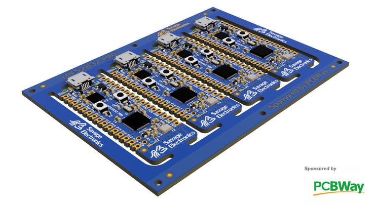
I have made a small panel for easy fabrication, This panel dimensions are 92x66mm including the tooling rails at the sides. In this panel I want to test several things that a usually do not order in a regular PCB, such as tooling rails with tooling holes, external fiducial, Logo with EING finish at the top tooling rail, solder mask and cooper restrictions for text and logos, and castellated holes in a routing job, v-score at the edges of the board as well on the tooling rails.

I quoted this panel in many PCB Manufacturing houses and order some boards for the best price in the market that includes all the characteristics described above with PCBWay. (Even cheaper than the well-know 2 USD – 5PCS PCB Manufacturing House).

These board are now getting manufactured, the customer service has been awesome so far, as I ask to place the UL Marking on the Top Silkscreen layer in the bottom layer of this panel and received a preview of confirmation of this requirement, and received awesome feedback regarding the Vscore and Solder mask capabilities.

Making this board possible required some knowledge in PCB Manufacturing that I will below describe the research and application.

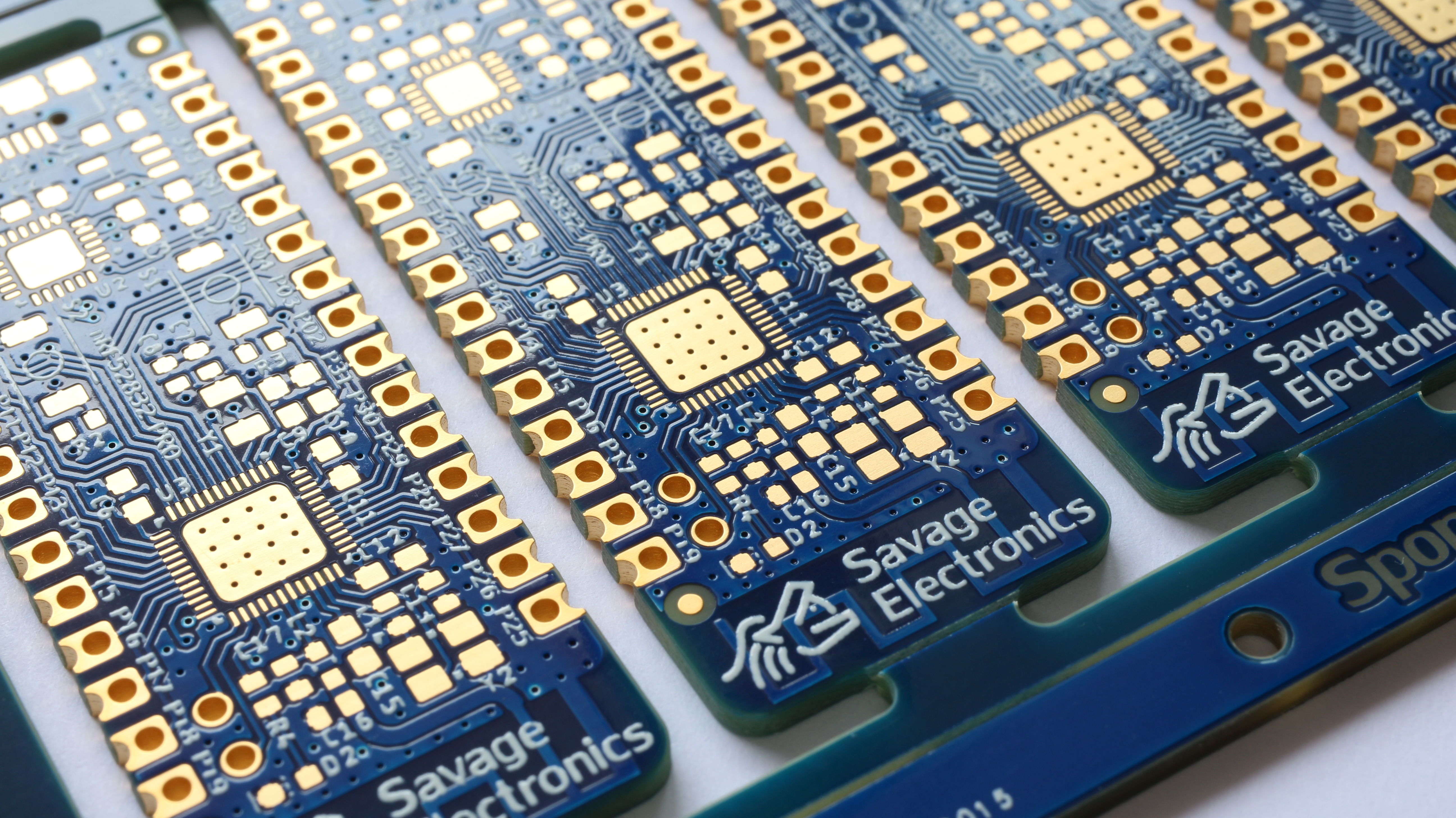
Castellated Holes: Also know as castellations are plated through-holes or vias at the edge of a board cut in the middle by a router making them pads that can be soldered to another PCB and make subassemblies.

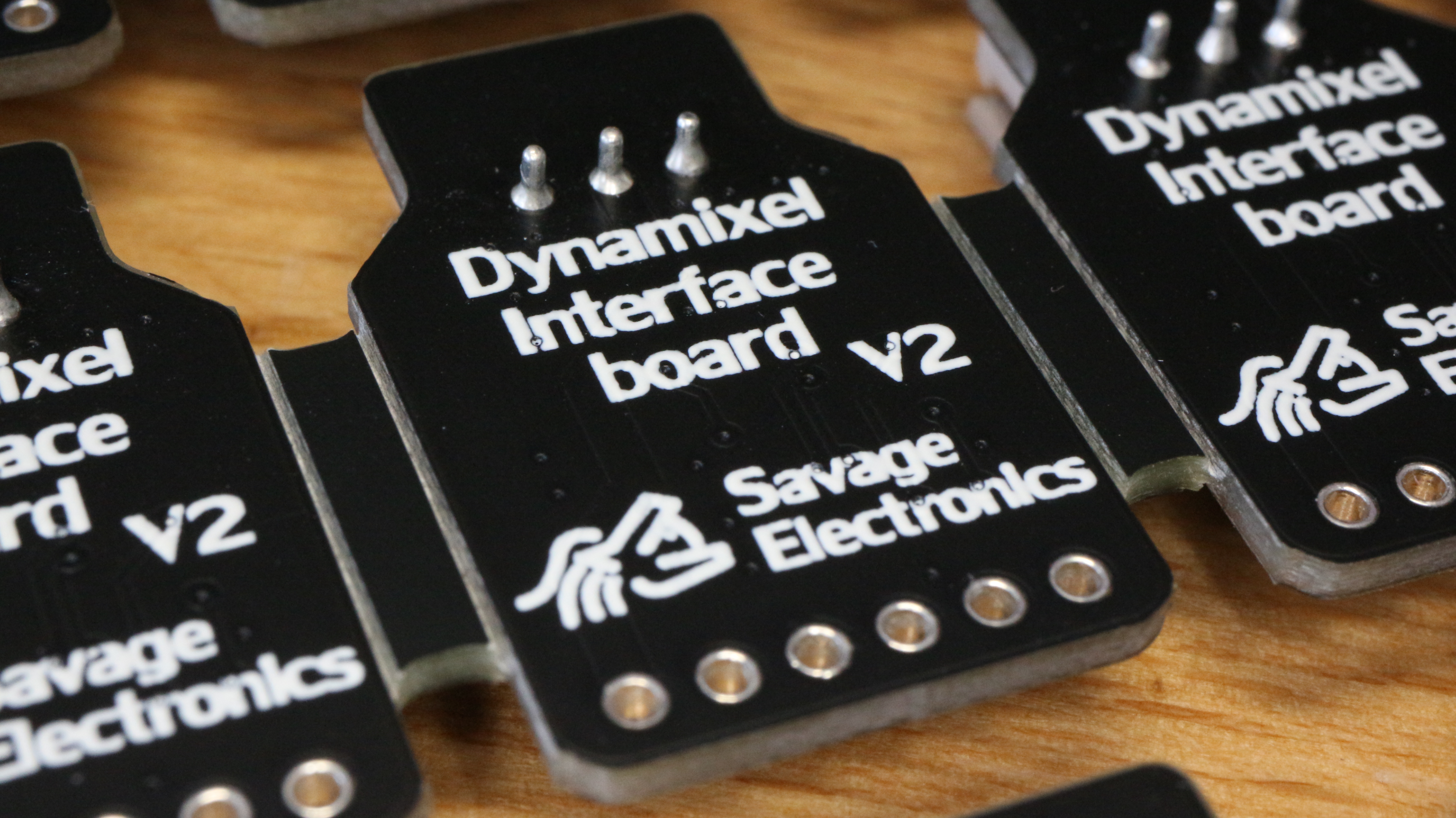
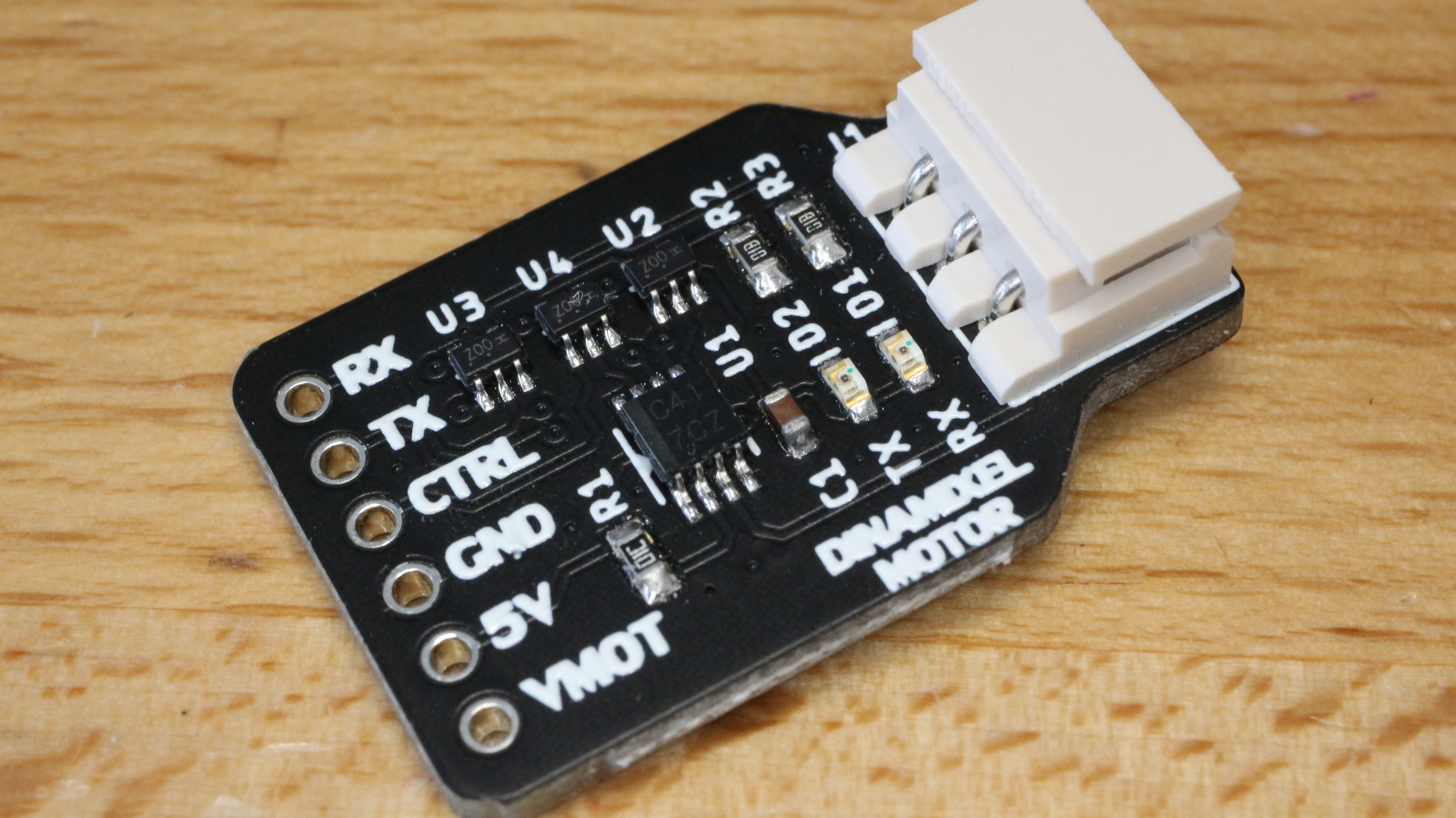
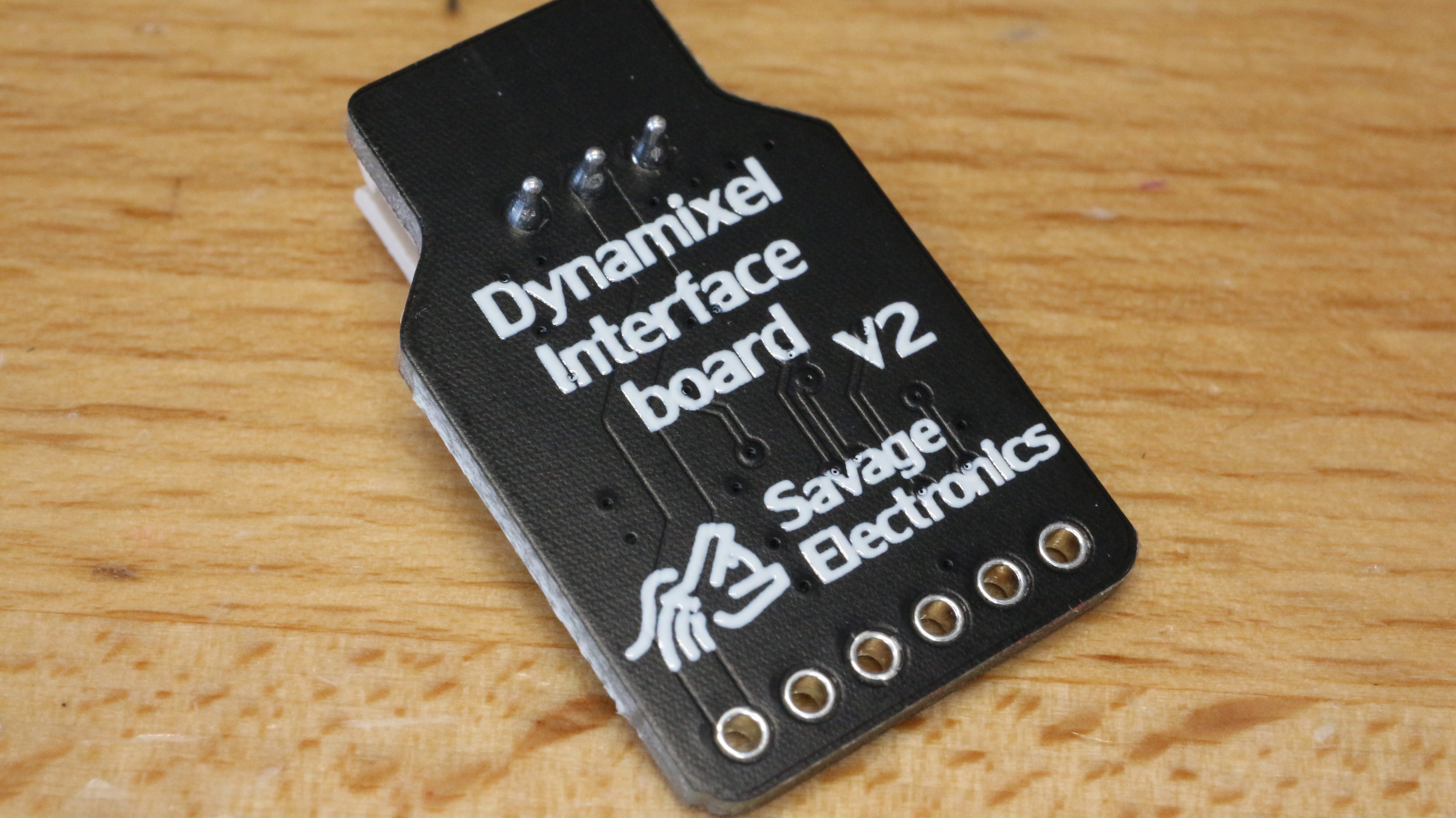
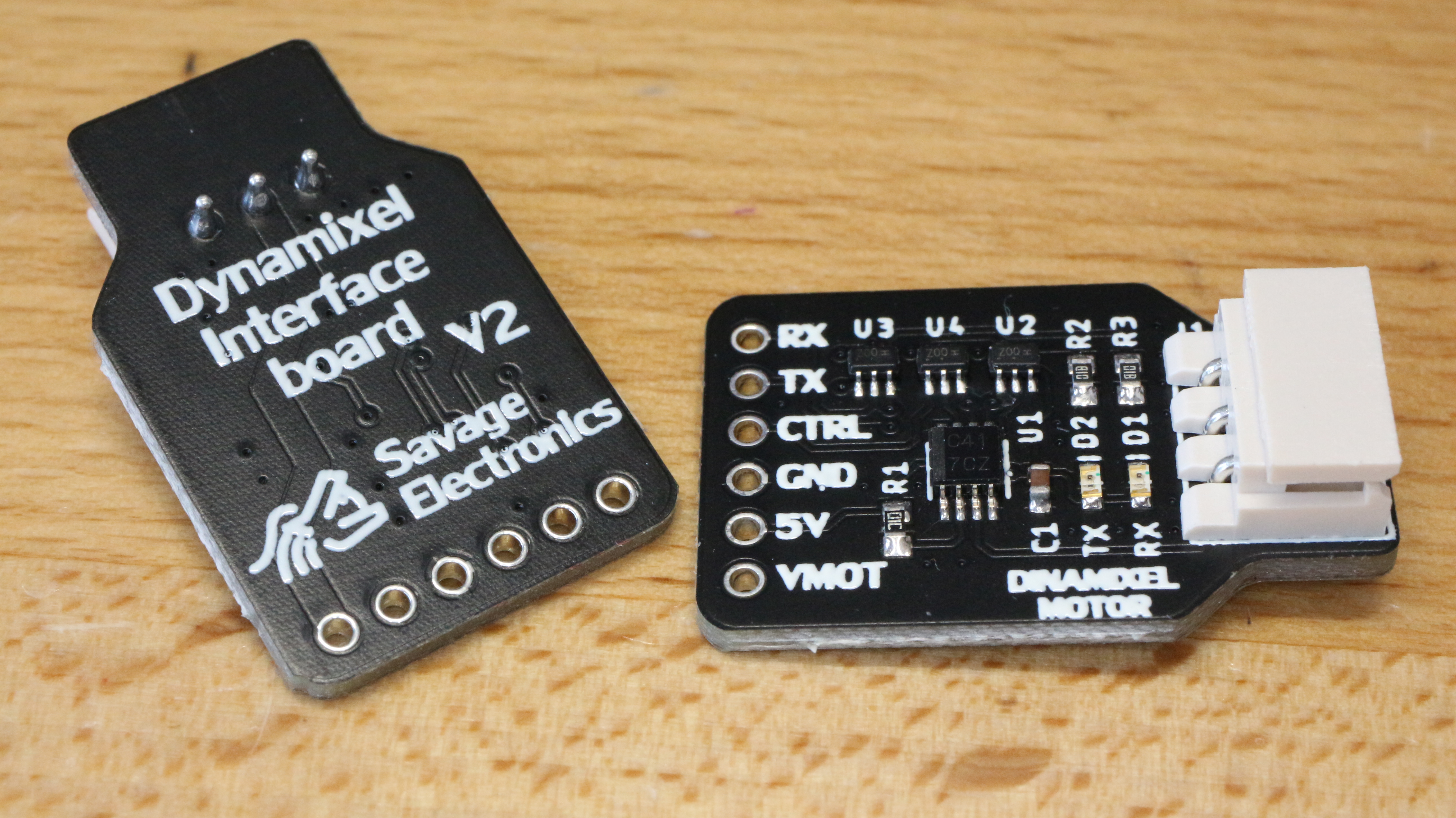
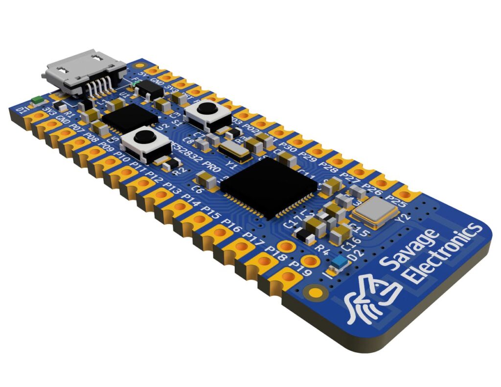
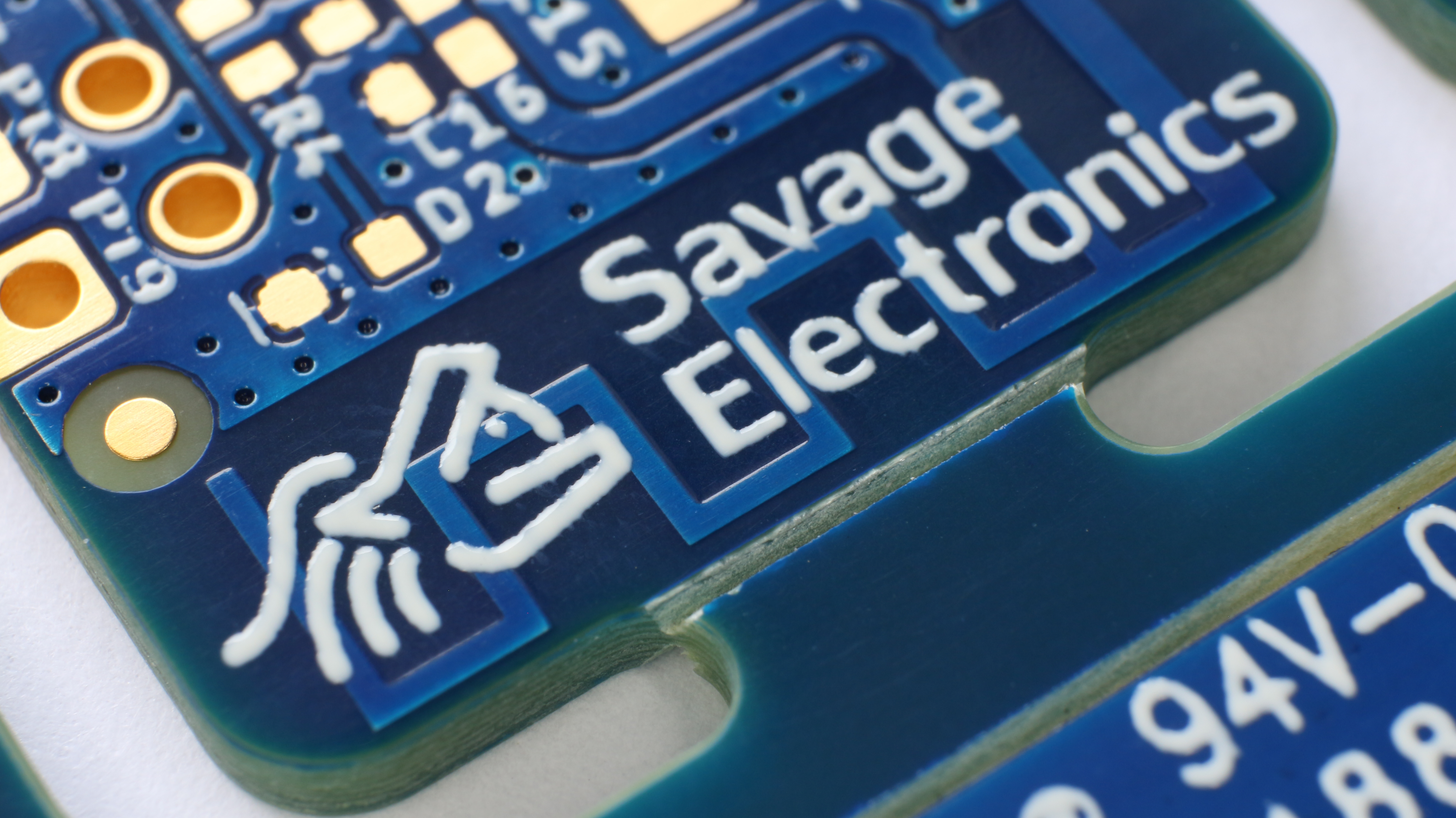
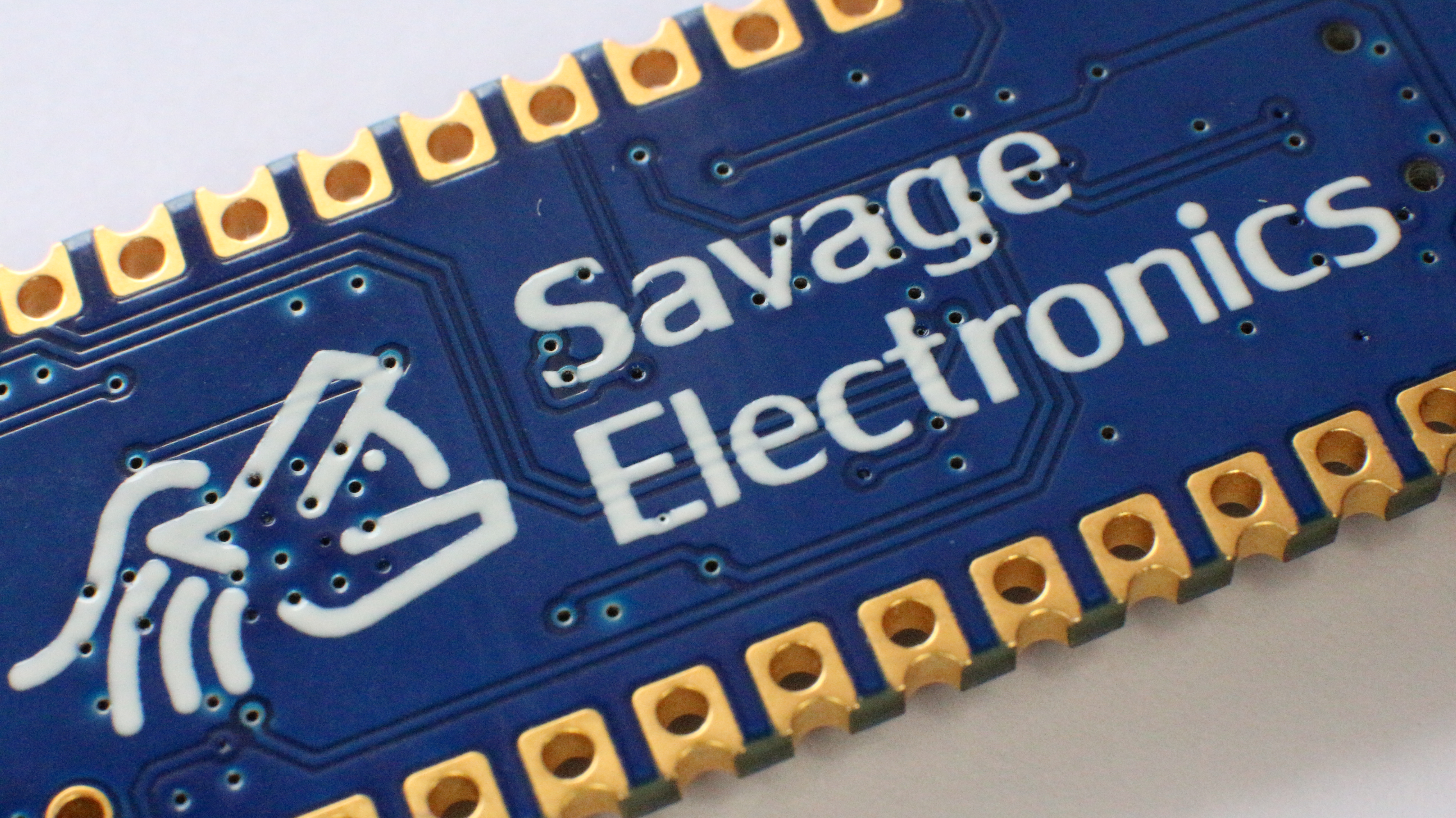
The PCBs have finally arrived, here are some photos.

If you are thinking about ordering some PCBs and start your own prototypes I recommend you to try PCBWay.

https://www.pcbway.com/

Dynamixel Interface Board V2

I have decided to redesign the Dynamixel interface and put it again in stock on my Tindie store, this redesign include some status LEDs that visually let you know if the motor is communicating to the motors and vice-versa, I have also decided to change the connector orientation which makes the board a little bit compact and more compatible with small dimensions projects.

The circuit for the LED indicators uses some NAND gates that let the user know when data is going to the servo and from the servo to the microcontroller without the need for a logic analyzer.  

This update is a very simple update and it does not affect the functionality of the interface, it is just a visual benefit for the user.

Here is the schematic in case you have the components and wish to make your own interface.

Test code:

#include <DynamixelSerial.h>

#define SERVO_ID  1
int Temperature,Voltage,Position; 

void setup(){
Dynamixel.setSerial(&Serial1); // &Serial - Arduino UNO/NANO/328P, &Serial1, &Serial2, &Serial3
Dynamixel.begin(1000000,2);    // Inicialize the servo at 1 Mbps and Pin Control 2
Serial.begin(9600);            // Begin Serial Comunication
}

void loop(){
  Temperature = Dynamixel.readTemperature(SERVO_ID); // Request and Print the Temperature
  Voltage = Dynamixel.readVoltage(SERVO_ID);         // Request and Print the Voltage
  Position = Dynamixel.readPosition(SERVO_ID);       // Request and Print the Position 

  Dynamixel.move(1,random(200,800));
 
  Serial.print("Temperature: ");                  // Print the variables in the Serial Monitor
  Serial.print(Temperature); Serial.print(" celcius, ");
  Serial.print("Voltage: ");
  Serial.print(float(Voltage)/10);Serial.print(" volts, ");
  Serial.print("Position: ");
  Serial.println(Position);

  delay(1000);
}

Arduino Dynamixel Library

After a long time here is an update in the Library for Dynamixel Sero Motors as the AX-12A.

These servos are pretty awesome, they seem the perfect solution for robotics as they can return several parameters as internal temperature, the voltage of operation, position, speed, torque, and all of this is accomplished as they have an internal microcontroller, the Atmega8 from Atmel which communicates over Half-Duplex UART TTL. This library helps you communicate with the Dynamixel Servos protocol V1.0 in any of the Serial channels of your Arduino.

The voltage of operation of these motors is recommended to be 11.1 volts, but it should work ok from 6V to 14V as the datasheet describes in the electrical ratings. Don’t forget to join the grounds of your motor’s power supply and the one from the microcontroller in other to level the signal voltage between them.

Power supply connection
Arduino UART pins connection

In order for this library to work and to ensure proper usage it is necessary to use a tri-state buffer IC, this can be achieved with a 74HC04 NOT gate and a 74HC126 tri-state buffer ICs ad Robotis suggests. I personally prefer the 74LS241 tri-state buffer with inverted enable pin input as is easy to connect and offers the same configuration in a single IC.

Don’t forget the VCC and GND IC power supply connections, VCC should be 5V

Download from my Github


https://github.com/JosueAGtz/dynamixelInterface