There has been sometimes that it has been hard to communicate with this type of smart motors, I don’t always remember the set ID or even the last configured baud rate for serial communication, or even the simple task of changing a single parameter requires to write a custom program to change that value to that specific motor, for that reason I decided to start building a handheld device that will make this kind of tasks easier and faster.
A simple UI in a TFT LCD will let configure these motors in a few steps, the project is going to integrate electronics used in other of my projects to make this development easier and faster, hoping to have feedback from the robotics community who have work with this kind of motors by letting me know the best path to follow.
In this first step I will have a first approach for the graphical interface, here are some ideas that I have tried, and the most recent one.
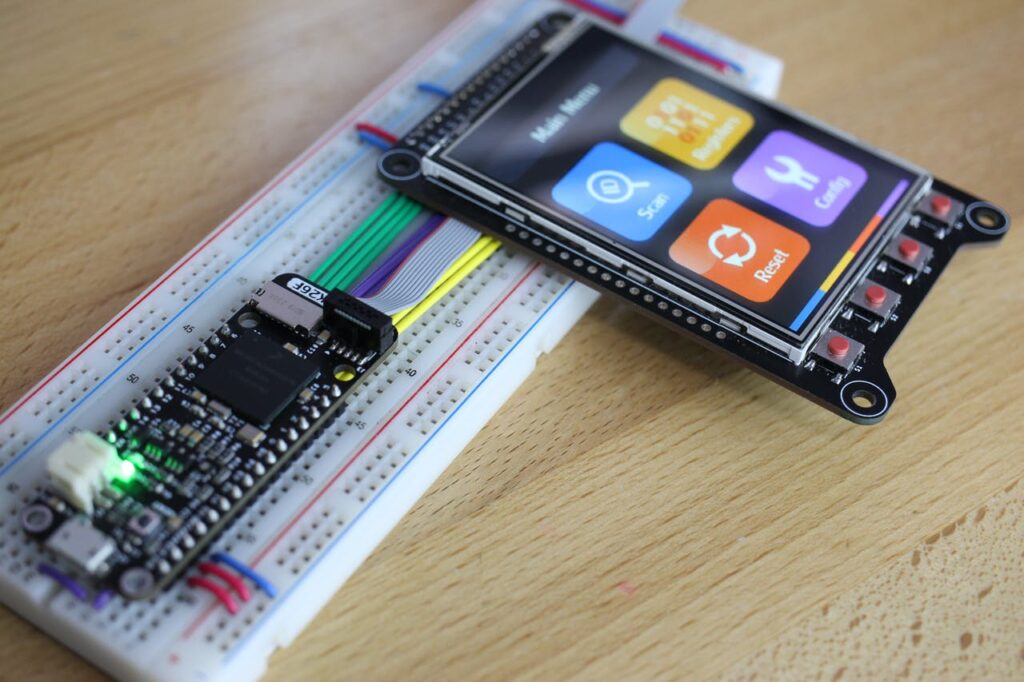
I will be using an ST7789V controller 2.8 inch TFT LCD for this project as I think it is a good size for the data it will work with. I will also be using the MK26F microcontroller that I have in a Feather format and a Dynamixel interface board for communication with the motors. So it needs to be all wired, connecting the SPI, ADCs, and GPIOs from the feather board to the TFT LCD Breakout board.
I have added some interesting things to the graphics for a more fluid and friendly interface as movement on the main menu icons, as shown in the next picture.

I have noticed that there are a lot of Dynamixel motors, the classic AX-12A use the protocol V1.0 but the newer one uses the V2.0 and also they change some registers address making this whole idea a bit difficult, I am still thinking how many motor models this device will support, as a first step I will make the firmware ready for the AX-12A and the XL-320 as I think are most popular one and also the cheapest.
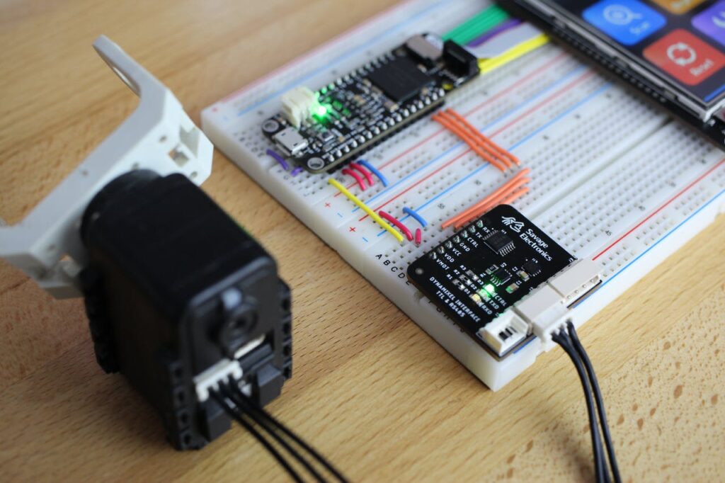
The first step is to port the Dynamixel library for Arduino that I wrote many years ago to my microcontroller and then also update the library to be compatible with the V2.0 Dynamixel protocol.
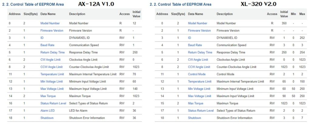
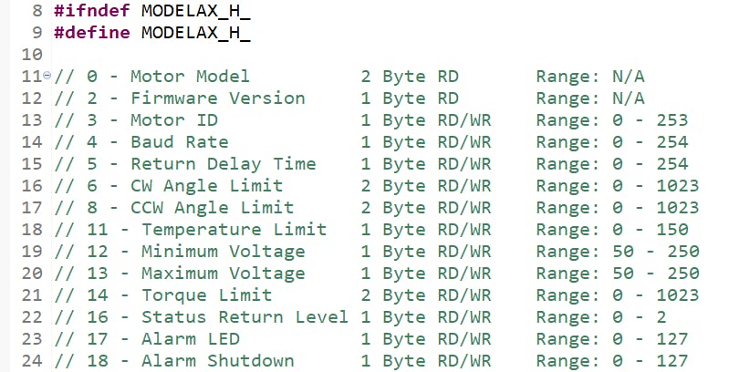
So there are some slight differences between registers address and all of this have to take in count when showing the info the configurator, so I have started to register this tables in a model file and maybe would be updated in a more compressible file in the future.
Motor scanning and selection menu
In order to test or modify the motor register, we need to scan and select the connected motors, for this task I have created a short function that Ping the bus and waits for each motor ID, and adds it to the motor list at a given baud rate and protocol.
for(motorID = 0; motorID < 254; motorID++){

             if( !(Dynamixelping(motorID,protocol) == -128) ){

                    motorList[motorIndex++] = motorID;

             }

             displaydrawRectangle(64,0,((motorID*240)/253),4,GREEN);

}
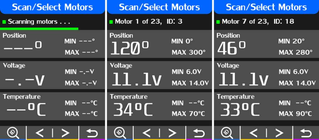
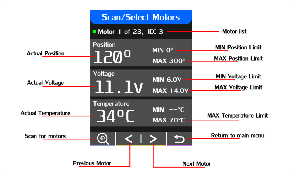
After the motor scanning, it’s useful to know certain values of the motor so I decided to read these and display them in the same window with the capability to scroll the motor list and at the same time select the motor of interest.
Configure Registers Window
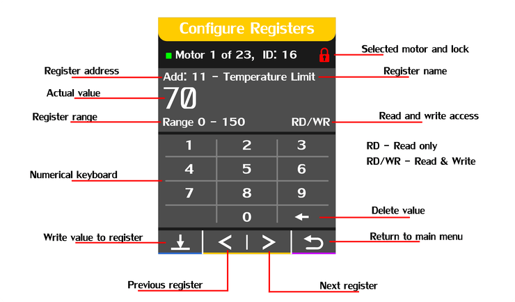
In this window will be able to read and write directly to register of the selected motor in the previous windows, it will be accessible to both the EEPROM and RAM registers in order to properly test the written values, limits, or alarms.The new values will be written on a numerical touchscreen keyboard.
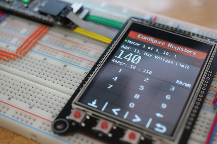
This window also shows if the EEPROM data is write-protected, in order to write the torque of the motor should be disabled, this can be done by writing a 0 to the Torque Enable register in address 24.
Factory Reset Window
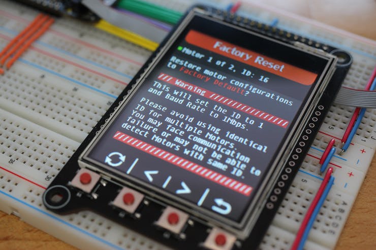
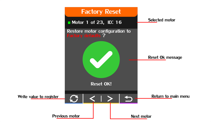
The factory reset window is a simple but very efficient way to restore motor parameters to factory defaults with a press of a button.
This option will perform a reset function on the Dynamixel instructions set, so all it been handled by the motor itself, the motor list is also accessible from this window but it has to be in consideration that motors should not have the same ID as it can cause errors in the communication.
When a reset has finished successfully this window will also inform and will let you continue with the reset operations that you may need for other motors.
Configuration Window
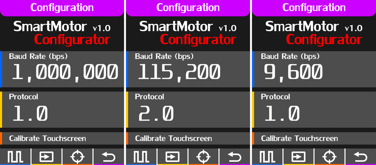
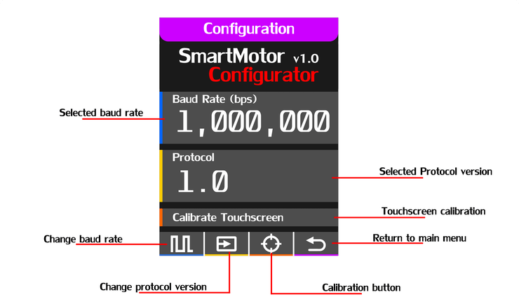
The configuration windows allow to change the Baud rate speed, the Dynamixel protocol and perform a touchscreen calibration if needed.
As you have already noticed the touchscreen calibration options are accessible with the tact switches in case that the touchscreen values have changed over time, the only action that needs the touchscreen is the keyboard on the register configuration window.


Hi Josue,
I am using your library with 3 Dynamixel AX-12A servos that are linked together and connected to an Arduino Mega. Everything worked fine, until somehow it stopped working completely. Now, I receive a “-1” as a reply to any message I send. I’ve tried resetting the servo using the reset(servo_id) function, but that too gives me a “-1”. Any idea on how to proceed? Your help is greatly appreciated!
Kind regards
Bas
By the way, I am using the DynamixelSerial3 library.
Somewhere on your old website you posted a message on how to debug the connections/hardware with the following code:
// ID. 1 Baud rate 1Mbps
void setup(){
Serial.begin(1000000);
pinMode(2,OUTPUT);
delay(1000);
}
void loop(){
digitalWrite(2,HIGH);
Serial.write(0xFF);
Serial.write(0xFF);
Serial.write(0x01);
Serial.write(0x04);
Serial.write(0x02);
Serial.write(0x2B);
Serial.write(0x01);
Serial.write(0xCC);
delay(10);
digitalWrite(2,LOW);
delay(1000);
Serial.print(“Returned Data: “);
while(Serial.available()){
Serial.print(“0x”);
Serial.print(Serial.read(),HEX);
Serial.print(” – “);
}
Serial.println(“Thats all, now you should be able to see the data.”);
delay(1000);
}
I am not sure whether it returns what is intended. This is an example of the output:
⸮⸮+⸮Returned Data: Thats all, now you should be able to see the data.
⸮⸮+⸮Returned Data: Thats all, now you should be able to see the data.
⸮⸮+⸮Returned Data: Thats all, now you should be able to see the data.
What can you make of this?
For that program to work you will need to identify in which serial port the motors are connected to, as the command data is static it will only work with ID = 1.
void setup(){
Serial.begin(115200);
Serial3.begin(1000000);
pinMode(2,OUTPUT);
delay(1000);
}
void loop(){
digitalWrite(2,HIGH);
Serial3.write(0xFF);
Serial3.write(0xFF);
Serial3.write(0x01);
Serial3.write(0x04);
Serial3.write(0x02);
Serial3.write(0x2B);
Serial3.write(0x01);
Serial3.write(0xCC);
delay(10);
digitalWrite(2,LOW);
delay(1000);
Serial.print(“Returned Data: “);
while(Serial.available()){
Serial.print(“0x”);
Serial.print(Serial.read(),HEX);
Serial.print(” – “);
}
Serial.println(“Thats all, now you should be able to see the data.”);
delay(1000);
}
I would try with the resetServo example provided with the library. Remember to connect just one motor at a time, and reconfigure your desired ID before daisy-chaining them.
Thank you for the response! This is all a bit new to me, so perhaps I am doing it completely wrong. I am using an older version of the library. In the modification history it says the last modification was on 15/01/2012. I am not sure whether I can upgrade to the newest library, without breaking the code that is build on top of it. Also, I only have the .h and .cpp file, so no examples. Are the examples for the older library version still available somewhere?
Also, on this website I see two libraries (SoftSerial & Serial). What is the difference? and in both example folders I cannot find the “resetServo” example.
Finally, the reset() function seems to take in an ID. Can it be that this ID (between 0-255, right?) has been reset somehow, and it can be any number now?
If it makes it easier for you to understand my problem, I could send you some pictures of the setup I have (Arduino Mega, with some custom shield), together with the library I am currently using? I have no clue whether this setup even allows me to reset the servos.
Should a setup that was initially able to control all three servos with your libary, also be capable of resetting the servo firmware? Last time I tried to use the reset() function i received a “-1”
Also, you say the code above only works with ID 1. Though, I am not sure what ID is currently set on the servo. Chances are that this ID is a number different then 1. How can I then change this ID to 1 if I cannot connect to the servo in the first place?
Yes, that code would not work if the ID and Baudrate are unknown. The motor should be reset to the factory defaults first.
Perhaps good to mention that I am using a Baudrate of 115200. This was the rate set in the code that was given to me. No clue whether I should set it to a different number when performing the reset. As I said earlier, my experience with actuators and hardware is limited…
The default ID is 1 and Baudrate is 1000000 (1Mbps).
There is not much change in the newer library, the difference between soft serial and Serial is that Softserial uses software for communications and Serial uses the hardware making it more stable and fast.
The reset example takes any servo at any baudrate or ID and restores it to the factory default settings.
#include
long BaudRates[] = {1000000,666667,500000,400000,333333,285714,250000,222222,
200000,181818,166667,153846,142857,133333,125000,117647,111111,105263,100000,
95238,90909,86957,83333,80000,76923,74074,71429,68966,66667,64516,62500,60606,
58824,57143,55556,54054,52632,51282,50000,48780,47619,46512,45455,44444,43478,
42553,41667,40816,40000,39216,38462,37736,37037,36364,35714,35088,34483,33898,
33333,32787,32258,31746,31250,30769,30303,29851,29412,28986,28571,28169,27778,
27397,27027,26667,26316,25974,25641,25316,25000,24691,24390,24096,23810,23529,
23256,22989,22727,22472,22222,21978,21739,21505,21277,21053,20833,20619,20408,
20202,20000,19802,19608,19417,19231,19048,18868,18692,18519,18349,18182,18018,
17857,17699,17544,17391,17241,17094,16949,16807,16667,16529,16393,16260,16129,
16000,15873,15748,15625,15504,15385,15267,15152,15038,14925,14815,14706,14599,
14493,14388,14286,14184,14085,13986,13889,13793,13699,13605,13514,13423,13333,
13245,13158,13072,12987,12903,12821,12739,12658,12579,12500,12422,12346,12270,
12195,12121,12048,11976,11905,11834,11765,11696,11628,11561,11494,11429,11364,
11299,11236,11173,11111,11050,10989,10929,10870,10811,10753,10695,10638,10582,
10526,10471,10417,10363,10309,10256,10204,10152,10101,10050,10000,9950,9901,
9852,9804,9756,9709,9662,9615,9569,9524,9479,9434,9390,9346,9302,9259,9217,
9174,9132,9091,9050,9009,8969,8929,8889,8850,8811,8772,8734,8696,8658,8621,
8584,8547,8511,8475,8439,8403,8368,8333,8299,8264,8230,8197,8163,8130,8097,
8065,8032,8000,7968,7937,7905,7874,7843};
void setup(){
pinMode(13,OUTPUT);
Dynamixel.setSerial(&Serial1);
for ( int i = 0; i <= 254;i++ ){ Dynamixel.begin(BaudRates[i],2); // inicializa la comunicacion. Dynamixel.reset(254); // Cambia el Baud a 1000000 ( 1Mbps ) } Dynamixel.begin(1000000,2); // Comprobacion. } void loop(){ digitalWrite(13,ON); Dynamixel.move(1,random(200,800)); delay(1000); digitalWrite(13,OFF); }